Toyota Venza: Removal
REMOVAL
PROCEDURE
1. REMOVE FRONT DOOR SCUFF PLATE LH
.gif)
2. REMOVE COWL SIDE TRIM SUB-ASSEMBLY LH
3. REMOVE LOWER NO. 1 INSTRUMENT PANEL FINISH PANEL
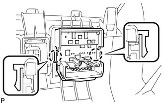
4. REMOVE OUTER MIRROR SWITCH ASSEMBLY
|
(a) Disengage the 2 claws and remove the outer mirror switch assembly. |
|
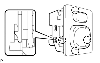
5. REMOVE OUTER MIRROR SWITCH
|
(a) Disengage the 4 claws and remove the outer mirror switch. |
|
 Components
COMPONENTS
ILLUSTRATION
...
 Inspection
INSPECTION
PROCEDURE
1. INSPECT OUTER MIRROR SWITCH ASSEMBLY (w/o Memory)
(a) The L position of the left/right adjustment switch: Measure the resistance
according to the value(s) in the table b ...
Other materials about Toyota Venza:
Relay
On-vehicle Inspection
ON-VEHICLE INSPECTION
PROCEDURE
1. INSPECT RR DEF RELAY
(a) Measure the resistance according to the value(s) in the table below.
Standard Resistance:
Tester Connection
Condition
...
Stereo Component Amplifier
Components
COMPONENTS
ILLUSTRATION
Removal
REMOVAL
PROCEDURE
1. REMOVE FRONT SEAT ASSEMBLY RH (for Manual Seat)
HINT:
Use the same procedure for the RH side and the LH side (See page
).
2. REMOVE FRONT SEAT ASSEMBLY RH (for Power Seat)
HINT:
...
Terminals Of Ecu
TERMINALS OF ECU
1. CHECK MAIN BODY ECU (DRIVER SIDE JUNCTION BLOCK ASSEMBLY)
(a) Disconnect the 2A, 2C and 2F main body ECU (driver side junction block assembly)
connectors.
(b) Measure the voltage and resistance according to the value(s) in the table ...

0.2006