Toyota Venza: Removal
REMOVAL
PROCEDURE
1. PRECAUTION
(See page .gif) )
)
NOTICE:
After turning the ignition switch off, waiting time may be required before disconnecting
the cable from the negative (-) battery terminal. Therefore, make sure to read the
disconnecting the cable from the negative (-) battery terminal notices before proceeding
with work (See page ).
2. DISCONNECT CABLE FROM NEGATIVE BATTERY TERMINAL
NOTICE:
When disconnecting the cable, some systems need to be initialized after the cable
is reconnected (See page ).
3. REMOVE UPPER CONSOLE PANEL SUB-ASSEMBLY (w/o Seat Heater System)
4. REMOVE UPPER CONSOLE PANEL SUB-ASSEMBLY (w/ Seat Heater System)
5. REMOVE NO. 2 CONSOLE BOX CARPET
6. REMOVE CONSOLE BOX ASSEMBLY
7. REMOVE AIR CONDITIONING CONTROL ASSEMBLY
8. REMOVE FRONT DOOR SCUFF PLATE RH
9. REMOVE COWL SIDE TRIM SUB-ASSEMBLY RH
10. REMOVE NO. 2 INSTRUMENT PANEL UNDER COVER SUB-ASSEMBLY
11. REMOVE LOWER INSTRUMENT PANEL SUB-ASSEMBLY
12. REMOVE SHIFT LEVER KNOB SUB-ASSEMBLY
13. REMOVE POSITION INDICATOR HOUSING ASSEMBLY
14. REMOVE CONSOLE BOX SUB-ASSEMBLY
15. REMOVE NO. 2 INSTRUMENT PANEL SPEAKER PANEL SUB-ASSEMBLY
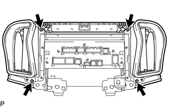
16. REMOVE NAVIGATION RECEIVER ASSEMBLY WITH BRACKET
|
(a) Remove the 4 bolts. |
|
.png)
(b) Disengage the 2 clips.
(c) Disconnect each connector and remove the navigation receiver assembly with bracket.
17. REMOVE INSTRUMENT CLUSTER CENTER FINISH PANEL SUB-ASSEMBLY
|
(a) Remove the 4 screws. |
|
|
(b) Disengage the 4 claws and remove the instrument cluster center finish panel sub-assembly. |
|
.png)
18. REMOVE STEREO COMPONENT TUNER ASSEMBLY WITH WIRE (w/ Satellite Radio)
19. REMOVE NO. 1 RADIO RECEIVER BRACKET
|
(a) Remove the 4 screws and No. 1 radio receiver bracket. |
|
.png)
20. REMOVE NO. 2 RADIO RECEIVER BRACKET
|
(a) Remove the 4 screws and No. 2 radio receiver bracket. |
|
.png)
21. REMOVE NAVIGATION RECEIVER ASSEMBLY
 Components
COMPONENTS
ILLUSTRATION
ILLUSTRATION
ILLUSTRATION
ILLUSTRATION
...
 Installation
INSTALLATION
PROCEDURE
1. INSTALL NAVIGATION RECEIVER ASSEMBLY
2. INSTALL NO. 2 RADIO RECEIVER BRACKET
(a) Install the No. 2 radio receiver bracket with the 4 screws.
Torque:
5.0 N·m {51 kgf· ...
Other materials about Toyota Venza:
Camshaft Position "A" Actuator Circuit (Bank 1) (P0010)
DESCRIPTION
The Variable Valve Timing (VVT) system adjusts the intake valve timing to improve
driveability. The engine oil pressure turns the VVT controller to adjust the valve
timing.
The camshaft timing oil control valve assembly is a solenoid valve an ...
Operation Check
OPERATION CHECK
1. CHECK POWER DOOR LOCK CONTROL OPERATION
NOTICE:
The following procedure is based on the assumption that the functions have not
been customized using the Techstream.
(a) Check basic functions.
(1) Check that all doors lock when the loc ...
Problem Symptoms Table
PROBLEM SYMPTOMS TABLE
HINT:
Use the table below to help determine the cause of problem symptoms.
If multiple suspected areas are listed, the potential causes of the symptoms
are listed in order of probability in the "Suspected Area" ...

0.1443