Toyota Venza: Inspection
INSPECTION
PROCEDURE
1. INSPECT OUTER MIRROR SWITCH ASSEMBLY (w/o Memory)
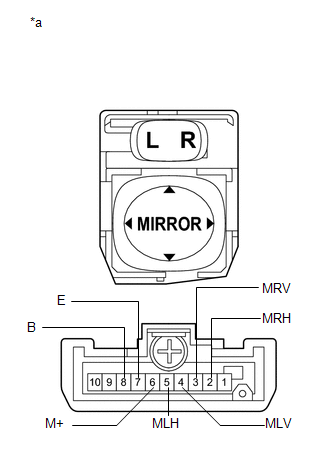
(a) The L position of the left/right adjustment switch: Measure the resistance according to the value(s) in the table below.
Standard Resistance (for Left Side):
|
Tester Connection |
Condition |
Specified Condition |
|---|---|---|
|
4 (MLV) - 8 (B) 6 (M+) - 7 (E) |
UP |
Below 1 Ω |
|
OFF |
10 kΩ or higher |
|
|
4 (MLV) - 7 (E) 6 (M+) - 8 (B) |
DOWN |
Below 1 Ω |
|
OFF |
10 kΩ or higher |
|
|
5 (MLH) - 8 (B) 6 (M+) - 7 (E) |
LEFT |
Below 1 Ω |
|
OFF |
10 kΩ or higher |
|
|
5 (MLH) - 7 (E) 6 (M+) - 8 (B) |
RIGHT |
Below 1 Ω |
|
OFF |
10 kΩ or higher |
|
*a |
Component without harness connected (Outer Mirror Switch Assembly) |
If the result is not as specified, replace the switch assembly.
(b) The R position of the left/right adjustment switch: Measure the resistance according to the value(s) in the table below.
Standard Resistance (for Right Side):
|
Tester Connection |
Condition |
Specified Condition |
|---|---|---|
|
3 (MRV) - 8 (B) 6 (M+) - 7 (E) |
UP |
Below 1 Ω |
|
OFF |
10 kΩ or higher |
|
|
3 (MRV) - 7 (E) 6 (M+) - 8 (B) |
DOWN |
Below 1 Ω |
|
OFF |
10 kΩ or higher |
|
|
2 (MRH) - 8 (B) 6 (M+) - 7 (E) |
LEFT |
Below 1 Ω |
|
OFF |
10 kΩ or higher |
|
|
2 (MRH) - 7 (E) 6 (M+) - 8 (B) |
RIGHT |
Below 1 Ω |
|
OFF |
10 kΩ or higher |
|
*a |
Component without harness connected (Outer Mirror Switch Assembly) |
If the result is not as specified, replace the switch assembly.
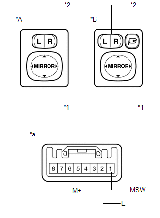
2. INSPECT OUTER MIRROR SWITCH ASSEMBLY (w/ Memory)
|
(a) Check the switch functions. (1) Measure the resistance according to the value(s) in the table below. Standard Resistance:
If the result is not as specified, replace the outer mirror switch assembly. |
|
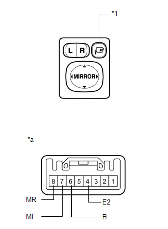
(b) Check the mirror retract switch.
|
(1) Measure the resistance according to the value(s) in the table below. Standard Resistance:
If the result is not as specified, replace the outer mirror switch assembly. |
|
 Removal
REMOVAL
PROCEDURE
1. REMOVE FRONT DOOR SCUFF PLATE LH
2. REMOVE COWL SIDE TRIM SUB-ASSEMBLY LH
3. REMOVE LOWER NO. 1 INSTRUMENT PANEL FINISH PANEL
4. REMOVE OUTER MIRROR SWITCH ASSEMBLY
...
 Installation
INSTALLATION
PROCEDURE
1. INSTALL OUTER MIRROR SWITCH
(a) Engage the 4 claws to install the outer mirror switch.
2. INSTALL OUTER MIRROR S ...
Other materials about Toyota Venza:
Open in Rear Floor Electrical Key Oscillator Circuit (B27A6)
DESCRIPTION
The certification ECU (smart key ECU assembly) generates a request signal and
sends it to the indoor electrical key oscillator (for center floor). To detect the
key inside the cabin, the indoor electrical key oscillator (for center floor) crea ...
Terminals Of Ecu
TERMINALS OF ECU
1. A/C AMPLIFIER
HINT:
Check from the rear of the connector while it is connected to the A/C amplifier.
Terminal No.
(Symbol)
Wiring Color
Terminal Description
Condition
Specified ...
No Signal from Transmitter ID1 (C2121/21-C2124/24,C2181/81-C2184/84)
DESCRIPTION
The tire pressure warning valve and transmitter installed in each tire and wheel
assembly measures the tire pressures. The measured values are transmitted as radio
waves to the tire pressure warning antenna and receiver on the body and then se ...

0.1157