Toyota Venza: System Diagram
SYSTEM DIAGRAM
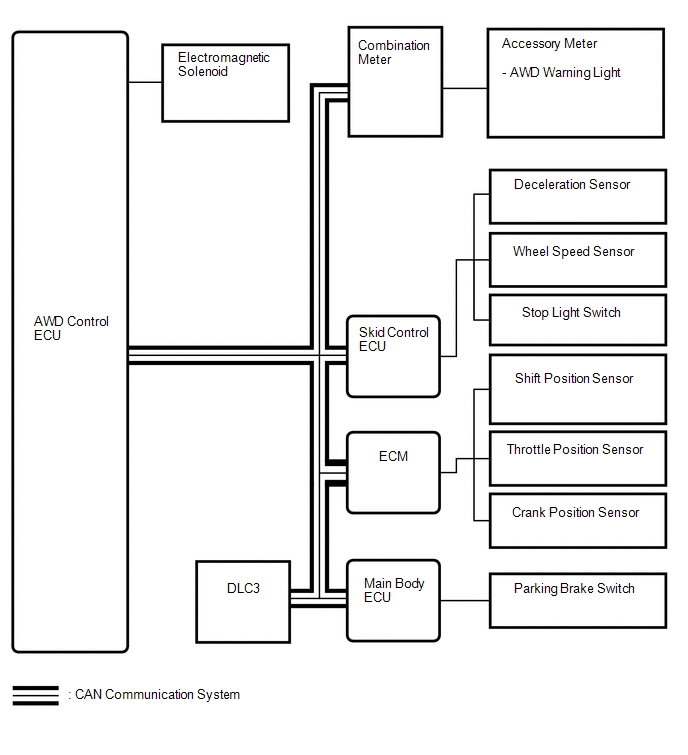 Communication Table
|
Transmitting ECU |
Receiving ECU |
Signal |
Communication Method |
|---|---|---|---|
|
Skid control ECU |
AWD control ECU |
|
CAN communication system |
|
ECM |
AWD control ECU |
|
CAN communication system |
|
Main body ECU |
AWD control ECU |
Parking brake switch signal |
CAN communication system |
|
AWD control ECU |
Combination meter |
AWD warning light signal |
CAN communication system |
 System Description
SYSTEM DESCRIPTION
1. FUNCTION OF MAIN COMPONENTS
Component
Function
Accessory Meter Assembly
AWD Warning Light
Illuminates to ...
 How To Proceed With Troubleshooting
CAUTION / NOTICE / HINT
HINT:
Use the following procedure listed to troubleshoot the Active Torque
Control 4WD system.
*: Use the Techstream.
PROCEDURE
1.
...
Other materials about Toyota Venza:
Fuel consumption display (vehicles with Display Audio system)
The actual display may differ from that shown in “Display Audio System Owner’s
Manual”.
• The information related to fuel consumption is also displayed on the multi-information
display. (, 204) • To reset the average fuel consumption data displa ...
Installation
INSTALLATION
PROCEDURE
1. INSTALL CENTER AIRBAG SENSOR ASSEMBLY
(a) Check that the ignition switch is off.
(b) Check that the cable is disconnected from the negative (-) battery terminal.
CAUTION:
Wait at least 90 seconds after disconnecting the cable fr ...
Reassembly
REASSEMBLY
PROCEDURE
1. INSTALL TRANSFER DRIVEN PINION REAR BEARING
(a) Using SST and a press, press the transfer driven pinion rear bearing
(outer race) to the case.
SST: 09950-60010
09951-00620
SST: 09950-70010
09951-07150
NO ...

0.1602