Toyota Venza: Components
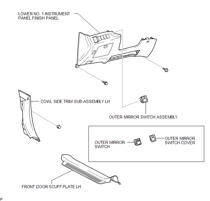
COMPONENTS
ILLUSTRATION

 Removal
REMOVAL
PROCEDURE
1. REMOVE FRONT DOOR SCUFF PLATE LH
2. REMOVE COWL SIDE TRIM SUB-ASSEMBLY LH
3. REMOVE LOWER NO. 1 INSTRUMENT PANEL FINISH PANEL
4. REMOVE OUTER MIRROR SWITCH ASSEMBLY
...
Other materials about Toyota Venza:
Components
COMPONENTS
ILLUSTRATION
ILLUSTRATION
ILLUSTRATION
ILLUSTRATION
ILLUSTRATION
...
Sound Quality is Bad Only when CD is Played (Volume is Too Low)
PROCEDURE
1.
REPLACE CD AND RECHECK
(a) Replace the CD with a new or known good one and check that the malfunction
disappears.
OK:
Malfunction disappears.
OK
END
NG
REPLACE ...
Test Mode Procedure
TEST MODE PROCEDURE
1. ENTER TEST MODE (SIGNAL CHECK MODE)
(a) Turn the ignition switch off.
(b) Connect the Techstream to the DLC3.
(c) Turn the ignition switch to ON.
(d) Check that the tire pressure warning light comes on for 3 seconds and then
goes ...
© 2016-2026 Copyright www.tovenza.com

0.1434
0.1434