Toyota Venza: Removal
REMOVAL
PROCEDURE
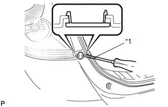
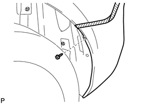
1. REMOVE REAR BUMPER PLATE LH
|
(a) Using a screwdriver with the tip wrapped with protective tape, disengage the 2 claws and remove the rear bumper plate LH. Text in Illustration
|
|
2. REMOVE REAR BUMPER PLATE RH
HINT:
Use the same procedure for the RH side and LH side.
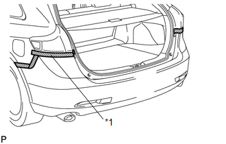
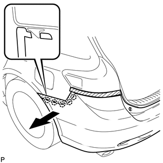
3. REMOVE REAR BUMPER ASSEMBLY
|
(a) Put protective tape around the rear bumper assembly. Text in Illustration
|
|
|
(b) Remove the 2 bolts and 2 screws. |
|
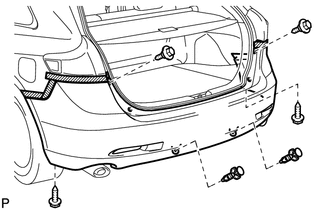
(c) Using a clip remover, remove the 2 clips.
|
(d) Remove the 2 screws and 2 clips. |
|
|
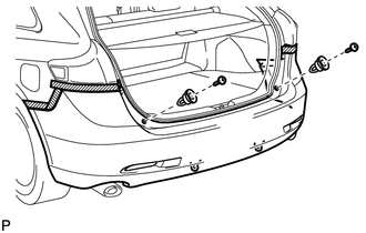
(e) Remove the screw. HINT: Use the same procedure for the RH side and LH side. |
|
|
(f) Disengage the 5 claws. HINT: Use the same procedure for the RH side and LH side. |
|
|
(g) Disengage the 6 claws as shown in the illustration. |
|
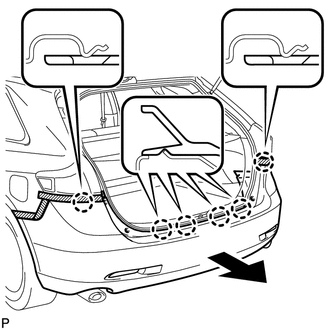
(h) w/ Intuitive Parking Assist System:
(1) Disconnect each connector.
(i) Remove the rear bumper assembly.
 Components
COMPONENTS
ILLUSTRATION
ILLUSTRATION
ILLUSTRATION
ILLUSTRATION
...
 Disassembly
DISASSEMBLY
PROCEDURE
1. REMOVE ULTRASONIC SENSOR CLIP (w/ Intuitive Parking Assist System)
2. REMOVE NO. 1 ULTRASONIC SENSOR (w/ Intuitive Parking Assist System)
3. REMOVE NO. 1 ULTRASONIC ...
Other materials about Toyota Venza:
Uniform Tire Quality Grading
This information has been prepared in accordance with regulations issued by the
National Highway Traffic Safety Administration of the U.S. Department of Transportation.
It provides the purchasers and/or prospective purchasers of Toyota vehicles with
infor ...
Interior lights list
Your Toyota is equipped with the illuminated entry system to assist in entering
the vehicle. Due to the function of the system, the lights shown in the following
illustration automatically turn on/off according to the presence of the electronic
key (vehi ...
Installation
INSTALLATION
CAUTION / NOTICE / HINT
HINT:
Use the same procedure for the LH side and RH side.
The following procedure is for the LH side.
PROCEDURE
1. INSTALL FRONT LOWER SUSPENSION ARM
(a) Install the front lower arm bushing stopper t ...

0.1161