Toyota Venza: Disassembly
DISASSEMBLY
PROCEDURE
1. REMOVE ULTRASONIC SENSOR CLIP (w/ Intuitive Parking Assist System)
.gif)
2. REMOVE NO. 1 ULTRASONIC SENSOR (w/ Intuitive Parking Assist System)
3. REMOVE NO. 1 ULTRASONIC SENSOR RETAINER (w/ Intuitive Parking Assist System)
4. REMOVE REAR BUMPER WIRE (w/ Intuitive Parking Assist System)
5. REMOVE REFLEX REFLECTOR ASSEMBLY LH
|
(a) Remove the screw. |
|
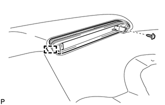
(b) Disengage the guide and remove the reflex reflector assembly LH.
6. REMOVE REFLEX REFLECTOR ASSEMBLY RH
HINT:
Use the same procedure for the RH side and LH side.
7. REMOVE REAR BUMPER SPOILER LH (for 1AR-FE)
|
(a) Remove the outside moulding retainer and clip. Text in Illustration
|
|
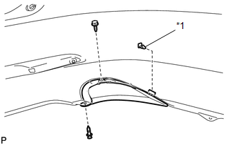
(b) Remove the screw and rear bumper spoiler LH.
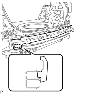
8. REMOVE REAR BUMPER SIDE RETAINER LH
|
(a) Remove the screw. |
|
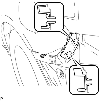
(b) Disengage the 2 claws and remove the rear bumper side retainer LH.
9. REMOVE REAR BUMPER SIDE RETAINER RH
HINT:
Use the same procedure for the RH side and LH side.
10. REMOVE NO. 2 REAR BUMPER SIDE SUPPORT LH
|
(a) Remove the screw. |
|
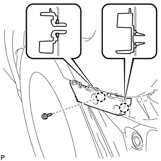
(b) Disengage the 2 claws and remove the No. 2 rear bumper side support LH.
11. REMOVE NO. 2 REAR BUMPER SIDE SUPPORT RH
HINT:
Use the same procedure for the RH side and LH side.
12. REMOVE REAR BUMPER ENERGY ABSORBER
|
(a) Disengage the 2 guides and remove the rear bumper energy absorber. |
|
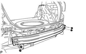
13. REMOVE NO. 1 REAR BUMPER REINFORCEMENT
|
(a) Remove the 6 nuts and No. 1 rear bumper reinforcement. |
|
 Removal
REMOVAL
PROCEDURE
1. REMOVE REAR BUMPER PLATE LH
(a) Using a screwdriver with the tip wrapped with protective tape, disengage
the 2 claws and remove the rear bumper plate LH.
Text ...
 Installation
INSTALLATION
PROCEDURE
1. INSTALL REAR BUMPER ASSEMBLY
(a) w/ Intuitive Parking Assist System:
(1) Connect each connector.
(b) Engage the 6 claws and install the rear bumper assembly a ...
Other materials about Toyota Venza:
Certification Ecu
Components
COMPONENTS
ILLUSTRATION
Removal
REMOVAL
PROCEDURE
1. DISCONNECT CABLE FROM NEGATIVE BATTERY TERMINAL
CAUTION:
Wait at least 90 seconds after disconnecting the cable from the negative (-)
battery terminal to disable the SRS system.
N ...
Tire information
Typical tire symbols
►Standard tire
►Compact spare tire
1. Tire size
2. DOT and Tire Identification Number (TIN)
3. Location of treadwear indicators
4. Tire ply composition and materials Plies are layers of rubber-coated parallel
cords ...
System Description
SYSTEM DESCRIPTION
1. TOUCH SWITCH OUTLINE
(a) Touch switches are touch-sensitive (interactive) switches operated by touching
the screen. When a switch is pressed, the outer film bends in to contact the inner
glass at the pressed position. By doing this, ...

0.1285