Toyota Venza: Inspection
INSPECTION
PROCEDURE
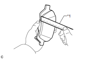
1. INSPECT PAD LINING THICKNESS
|
(a) Using a ruler, measure the pad lining thickness. Text in Illustration
Standard thickness of a new pad: 10.0 mm (0.394 in.) Minimum thickness: 1.0 mm (0.0394 in.) If the pad lining thickness is equal to or less than the minimum, replace the brake pads with a disc brake pad kit. HINT: Be sure to check the wear of the rear disc after replacing the brake pads with new ones. |
|
2. INSPECT REAR DISC BRAKE PAD SUPPORT PLATE
(a) Make sure that the rear disc brake pad support plates have sufficient rebound, no deformation, cracks or wear, and that all rust and dirt are removed. If necessary, replace the rear disc brake pad support plates.
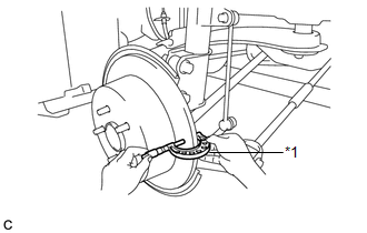
3. INSPECT DISC THICKNESS
|
(a) Using a micrometer, measure the disc thickness. Text in Illustration
Standard Thickness of a new disc: 10.0 mm (0.394 in.) Minimum Thickness: 9.0 mm (0.354 in.) HINT: If the disc thickness is less than the minimum, replace the rear disc. |
|
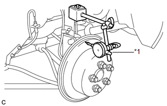
4. INSPECT DISC RUNOUT
(a) Inspect the rear axle hub bearing looseness and axle hub runout (for 2WD:
See page .gif) , for AWD: See page
).
, for AWD: See page
).
|
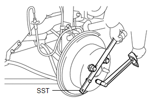
(b) Using SST to hold the disc, tighten the disc with the 5 hub nuts. SST: 09330-00021 Torque: 103 N·m {1050 kgf·cm, 76 ft·lbf} |
|
|
(c) Using a dial indicator, measure the disc runout 10 mm (0.394 in.) away from the outer edge of the rear disc. Text in Illustration
Maximum disc runout: 0.15 mm (0.00591 in.) If the runout exceeds the maximum, change the installation position of the disc to minimize runout. If the runout exceeds the maximum even when the installation position is changed, grind the disc. If the disc thickness is less than the minimum, replace the rear disc. NOTICE: Keep the magnetic parts of the dial indicator away from the axle hub and speed sensor. |
|
(d) Remove the 5 hub nuts and rear disc.
 Removal
REMOVAL
CAUTION / NOTICE / HINT
HINT:
Use the same procedure for the LH side and RH side.
The following procedure listed is for the LH side.
PROCEDURE
1. REMOVE REAR WHEEL
2. D ...
 Installation
INSTALLATION
PROCEDURE
1. TEMPORARILY TIGHTEN REAR DISC BRAKE BLEEDER PLUG
(a) Temporarily tighten the rear disc brake bleeder plug.
HINT:
Fully tighten the rear disc brake bleeder plug after ble ...
Other materials about Toyota Venza:
Driver Side Door Entry Unlock Function does not Operate
DESCRIPTION
If the driver door entry lock function operates normally, but its entry unlock
function does not, this means that the request code from the driver door is being
output normally. In this case, a malfunction in the touch sensor circuit (from the ...
Terminals Of Ecu
TERMINALS OF ECU
1. COMBINATION METER ASSEMBLY
(a) Measure the voltage and resistance according to the value(s) in the table
below.
Terminal No. (Symbol)
Wiring Color
Terminal Description
Condition
...
Inspection
INSPECTION
PROCEDURE
1. INSPECT SPIRAL CABLE
(a) Visually check for defects with the spiral cable removed from the vehicle.
(1) The defects are as follows:
Scratches on the spiral cable
Small cracks the spiral cable
Dents on the spiral cabl ...

0.17