Toyota Venza: Components
COMPONENTS
ILLUSTRATION
ILLUSTRATION
ILLUSTRATION
ILLUSTRATION
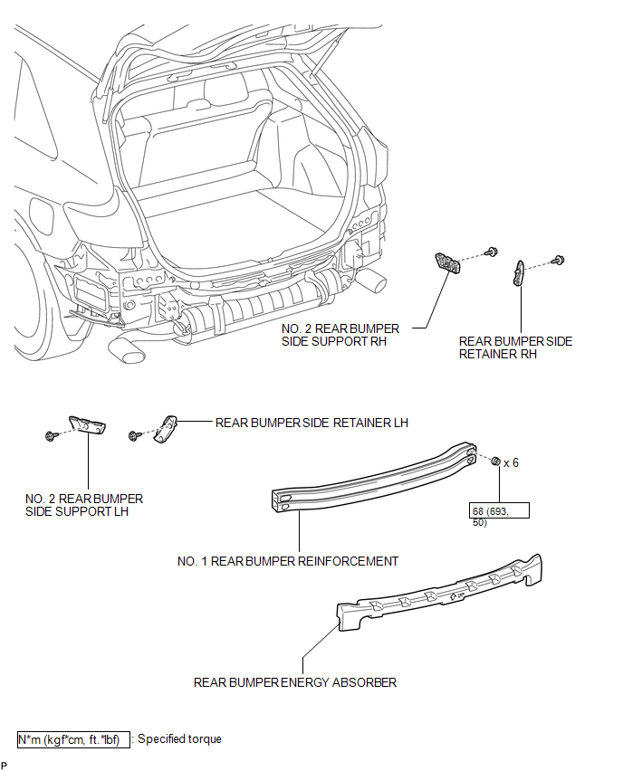
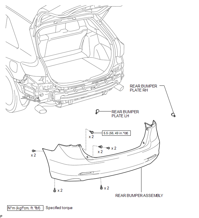
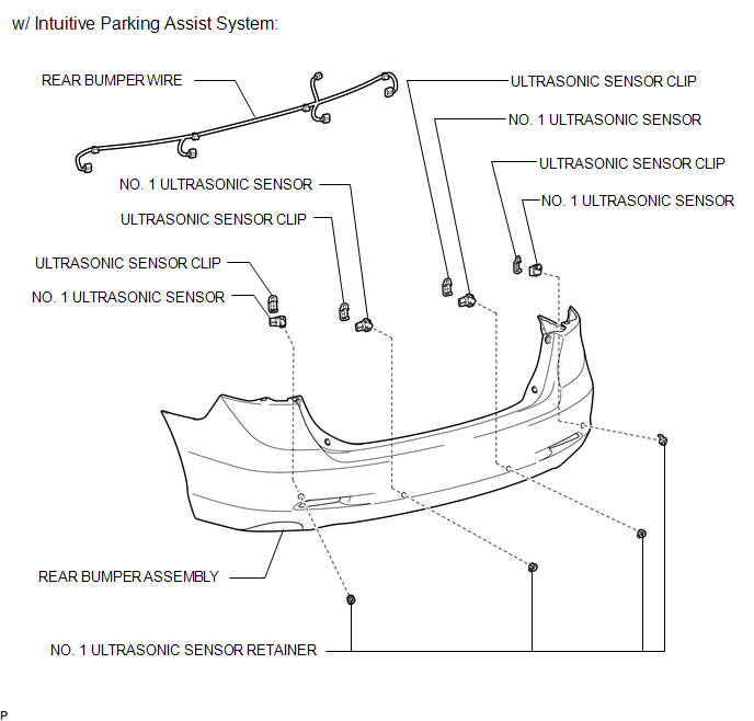
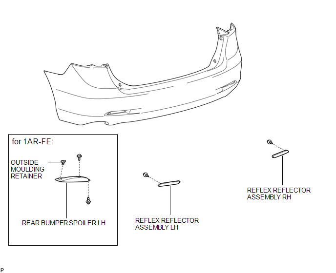
 Rear Bumper
...
 Removal
REMOVAL
PROCEDURE
1. REMOVE REAR BUMPER PLATE LH
(a) Using a screwdriver with the tip wrapped with protective tape, disengage
the 2 claws and remove the rear bumper plate LH.
Text ...
Other materials about Toyota Venza:
Operation Check
OPERATION CHECK
1. CHECK AUTO OPERATION
NOTICE:
Make sure that initialization is completed before inspection (See page
).
HINT:
When pressing the switch for 0.3 seconds or less, the roof glass moves but auto
operation does not operate.
(a) Turn the i ...
Installation
INSTALLATION
PROCEDURE
1. INSTALL POWER BACK DOOR UNIT ASSEMBLY
(a) Install the power back door unit with the 4 bolts.
Torque:
13 N·m {133 kgf·cm, 10 ft·lbf}
(b) Connect the connector.
2. ...
Engine coolant
The coolant level is satisfactory if it is between the “F” and “L” lines on the
reservoir when the engine is cold.
1. Reservoir cap
2. Full
3. Low
If the level is on or below the “L” line, add coolant up to the “F” line.
- If the ...

0.1313