Toyota Venza: Removal
REMOVAL
CAUTION / NOTICE / HINT
HINT:
When installing new name plates and emblem, heat the vehicle body, name plates and emblem using a heat light.
Heating Temperature|
Item |
Temperature |
|---|---|
|
Vehicle Body |
40 to 60°C (104 to 140°F) |
|
Emblem, Name Plate |
20 to 30°C (68 to 86°F) |
NOTICE:
Do not heat the vehicle body, name plates or emblem excessively.
PROCEDURE
1. REMOVE HOOD EMBLEM
|
(a) Put protective tape around the hood emblem. Text in Illustration
|
|
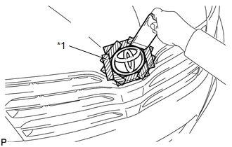
(b) Using a moulding remover, peel off the double-sided tape to remove the hood emblem.
NOTICE:
- If reusing the emblem, take care not to damage the hood emblem.
- Be careful not to damage the vehicle body.
2. REMOVE NO. 1 BACK DOOR EMBLEM
|
(a) Put protective tape around the No. 1 back door emblem. Text in Illustration
|
|
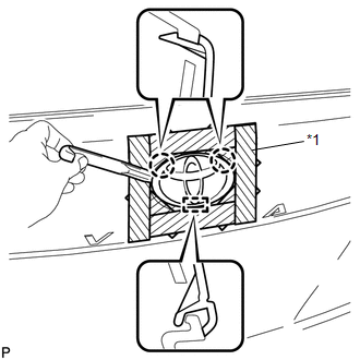
(b) Using a moulding remover, disengage the 2 claws.
NOTICE:
- If reusing the emblem, take care not to damage the No. 1 back door emblem.
- Be careful not to damage the vehicle body.
(c) Disengage the guide and remove the No. 1 back door emblem.
3. REMOVE NO. 2 BACK DOOR NAME PLATE
|
(a) Put protective tape around the No. 2 back door name plate. Text in Illustration
|
|
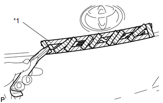
(b) Using a moulding remover, peel off the double-sided tape to remove the No. 2 back door name plate.
NOTICE:
- If reusing the name plate, take care not to damage the No. 2 back door name plate.
- Be careful not to damage the vehicle body.
4. REMOVE NO. 3 BACK DOOR NAME PLATE (for AWD)
|
(a) Put protective tape around the No. 3 back door name plate. Text in Illustration
|
|
(b) Using a moulding remover, peel off the double-sided tape to remove the No. 3 back door name plate.
NOTICE:
- If reusing the name plate, take care not to damage the No. 3 back door name plate.
- Be careful not to damage the vehicle body.
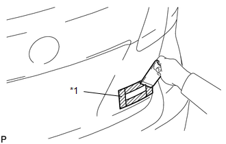
5. REMOVE NO. 4 LUGGAGE COMPARTMENT DOOR PLATE (w/ Grade Mark)
|
(a) Put protective tape around the No. 4 luggage compartment door plate. Text in Illustration
|
|
(b) Using a moulding remover, peel off the double-sided tape to remove the No. 4 luggage compartment door plate.
NOTICE:
- If reusing the door plate, take care not to damage the No. 4 luggage compartment door plate.
- Be careful not to damage the vehicle body.
 Components
COMPONENTS
ILLUSTRATION
...
 Installation
INSTALLATION
CAUTION / NOTICE / HINT
HINT:
When installing new name plates and emblem, heat the vehicle body, name plates
and emblem using a heat light.
Heating Temperature
Item
...
Other materials about Toyota Venza:
Navigation Receiver Assembly Communication Stop Mode
DESCRIPTION
Detection Item
Symptom
Trouble Area
Navigation Receiver Assembly Communication Stop Mode
"Display and Navigation (AVN1)" is not displayed on the "CAN
Bus ...
Problem Symptoms Table
PROBLEM SYMPTOMS TABLE
HINT:
Use the table below to help determine the cause of problem symptoms. If multiple
suspected areas are listed, the potential causes of the symptoms are listed in order
of probability in the "Suspected Area" column of ...
Replacement
REPLACEMENT
PROCEDURE
1. RECOVER REFRIGERANT FROM REFRIGERATION SYSTEM
(a) Start up the engine.
(b) Turn the A/C switch on.
(c) Operate the cooler compressor at an engine speed of approximately 1000 rpm
for 5 to 6 minutes to circulate the refrigerant. T ...

0.1353