Toyota Venza: Components
COMPONENTS
ILLUSTRATION
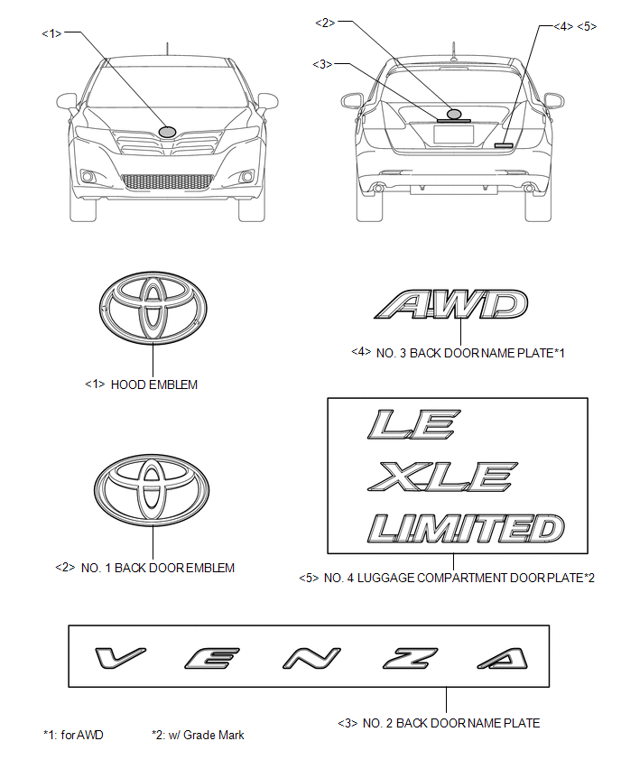
 Name Plate
...
 Removal
REMOVAL
CAUTION / NOTICE / HINT
HINT:
When installing new name plates and emblem, heat the vehicle body, name plates
and emblem using a heat light.
Heating Temperature
Item
...
Other materials about Toyota Venza:
Entire Combination Meter does not Operate
DESCRIPTION
This circuit is the power source circuit for the meter. This circuit provides
two types of power sources; one is a constant power source mainly used as a backup
power source, and the other is an IG power source mainly used for signal transmiss ...
Ultrasonic Sensor(for Front Side)
Components
COMPONENTS
ILLUSTRATION
Removal
REMOVAL
PROCEDURE
1. REMOVE FRONT BUMPER ASSEMBLY
(See page )
2. REMOVE NO. 1 ULTRASONIC SENSOR
(a) Disengage the 2 claws to remove the No. 1 ultrasonic sensor.
HINT:
Use the same proc ...
Operation Check
OPERATION CHECK
1. CHECK WINDOW LOCK SWITCH
HINT:
Before performing the window lock switch operation check, make sure that the
window lock switch is off (the switch is not pushed in).
(a) Check that the front passenger and rear windows cannot be operat ...

0.1639