Toyota Venza: Removal
REMOVAL
PROCEDURE
1. DISCONNECT CABLE FROM NEGATIVE BATTERY TERMINAL
CAUTION:
Wait at least 90 seconds after disconnecting the cable from the negative (-) battery terminal to disable the SRS system.
NOTICE:
When disconnecting the cable, some systems need to be initialized after the cable
is reconnected (See page .gif) ).
).
2. REMOVE FRONT SEAT ASSEMBLY LH (for Manual Seat)
HINT:
Refer to the procedure up to Remove Front Seat Assembly (See page
).
3. REMOVE FRONT SEAT ASSEMBLY LH (for Power Seat)
HINT:
Refer to the procedure up to Remove Front Seat Assembly (See page
)
4. REMOVE FRONT SEAT ASSEMBLY RH (for Manual Seat)
HINT:
Perform the same procedure as the LH side.
5. REMOVE FRONT SEAT ASSEMBLY RH (for Power Seat)
HINT:
Perform the same procedure as the LH side.
6. REMOVE UPPER CONSOLE PANEL SUB-ASSEMBLY (w/o Seat Heater System)
7. REMOVE UPPER CONSOLE PANEL SUB-ASSEMBLY (w/ Seat Heater System)
8. REMOVE NO. 2 CONSOLE BOX CARPET
9. REMOVE CONSOLE BOX ASSEMBLY
10. REMOVE AIR CONDITIONING CONTROL ASSEMBLY
11. REMOVE FRONT DOOR SCUFF PLATE LH
12. REMOVE COWL SIDE TRIM SUB-ASSEMBLY LH
13. REMOVE LOWER NO. 1 INSTRUMENT PANEL FINISH PANEL
14. REMOVE FRONT DOOR SCUFF PLATE RH
15. REMOVE COWL SIDE TRIM SUB-ASSEMBLY RH
16. REMOVE NO. 2 INSTRUMENT PANEL UNDER COVER SUB-ASSEMBLY
17. REMOVE LOWER INSTRUMENT PANEL SUB-ASSEMBLY
18. REMOVE SHIFT LEVER KNOB SUB-ASSEMBLY
19. REMOVE POSITION INDICATOR HOUSING ASSEMBLY
20. REMOVE CONSOLE BOX SUB-ASSEMBLY
21. REMOVE NO. 4 CENTER MEMBER FLOOR REINFORCE SUB-ASSEMBLY
(a) Turn back the floor carpet.
|
(b) Remove the 7 bolts and No. 4 center member floor reinforce sub-assembly. |
|
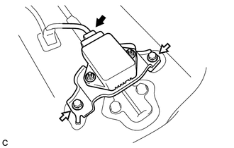
22. REMOVE YAW RATE AND ACCELERATION SENSOR
(a) Disconnect the connector from the yaw rate and acceleration sensor with bracket.
|
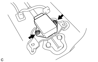
(b) Remove the 2 bolts and yaw rate and acceleration sensor with bracket. |
|
|
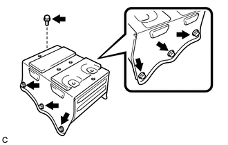
(c) Remove the 2 nuts and yaw rate and acceleration sensor from the bracket. |
|
 Components
COMPONENTS
ILLUSTRATION
ILLUSTRATION
ILLUSTRATION
...
 Installation
INSTALLATION
PROCEDURE
1. INSTALL YAW RATE AND ACCELERATION SENSOR
(a) Install the yaw rate and acceleration sensor to the bracket with
the 2 nuts.
Torque:
5.0 N·m {51 kgf·c ...
Other materials about Toyota Venza:
Input / Turbine Speed Sensor Circuit Malfunction (P0715,P0717)
DESCRIPTION
This sensor detects the rotation speed of the turbine which shows the input revolution
(speed) of the transaxle. By comparing the input turbine speed signal (NT) with
the counter gear speed sensor signal (NC), the TCM detects the shift timing ...
Disassembly
DISASSEMBLY
PROCEDURE
1. REMOVE SEAT ADJUSTER COVER CAP LH
(a) Using a screwdriver wrapped with protective tape, disengage the 3
claws and remove the seat adjuster cover cap LH.
Text in Illustration
*1
...
Readiness Monitor Drive Pattern
READINESS MONITOR DRIVE PATTERN
1. PURPOSE OF READINESS TESTS
The On-Board Diagnostic (OBD II) system is designed to monitor the performance
of emission related components, and indicate any detected abnormalities
using DTCs (Diagnostic Trouble ...

0.1342