Toyota Venza: Installation
INSTALLATION
CAUTION / NOTICE / HINT
HINT:
When installing new name plates and emblem, heat the vehicle body, name plates and emblem using a heat light.
Heating Temperature|
Item |
Temperature |
|---|---|
|
Vehicle Body |
40 to 60°C (104 to 140°F) |
|
Emblem, Name Plate |
20 to 30°C (68 to 86°F) |
NOTICE:
Do not heat the vehicle body, name plates or emblem excessively.
PROCEDURE
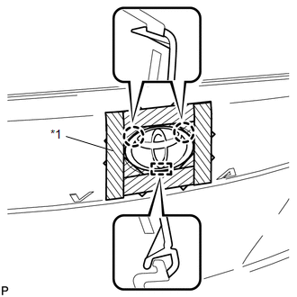
1. INSTALL NO. 1 BACK DOOR EMBLEM
|
(a) Install the No. 1 back door emblem with the guide and 2 claws. Text in Illustration
NOTICE: Be careful not to damage the vehicle body. |
|
2. INSTALL NO. 2 BACK DOOR NAME PLATE
(a) Clean the vehicle body surface.
(1) Using a heat light, heat the vehicle body surface.
(2) Remove any double-sided tape from the vehicle body.
(3) Wipe off any tape adhesive residue with cleaner.
(b) Clean the name plate (if reusing the name plate).
(1) Using a heat light, heat the name plate.
(2) Remove the double-sided tape from the name plate.
(3) Wipe off any tape adhesive residue with cleaner.
(4) Apply new double-sided tape to the name plate.
(c) Install the No. 2 back door name plate.
(1) Using a heat light, heat the vehicle body and the No. 2 back door name plate.
(2) Remove the release paper from the No. 2 back door name plate.
HINT:
After removing the release paper, keep the exposed adhesive free from foreign matter.
(3) Install the No. 2 back door name plate as shown in the illustration.
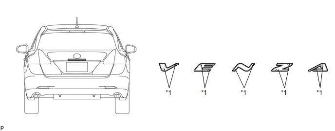 Text in Illustration
|
*1 |
Location Pin |
- |
- |
3. INSTALL NO. 3 BACK DOOR NAME PLATE (for AWD)
(a) Clean the vehicle body surface.
(1) Using a heat light, heat the vehicle body surface.
(2) Remove any double-sided tape from the vehicle body.
(3) Wipe off any tape adhesive residue with cleaner.
(b) Clean the name plate (if reusing the name plate).
(1) Using a heat light, heat the name plate.
(2) Remove the double-sided tape from the name plate.
(3) Wipe off any tape adhesive residue with cleaner.
(4) Apply new double-sided tape to the name plate.
(c) Install the No. 3 back door name plate.
(1) Using a heat light, heat the vehicle body and the new No. 3 back door name plate.
(2) Remove the release paper from the No. 3 back door name plate.
HINT:
After removing the release paper, keep the exposed adhesive free from foreign matter.
(3) Install the No. 3 back door name plate as shown in the illustration.
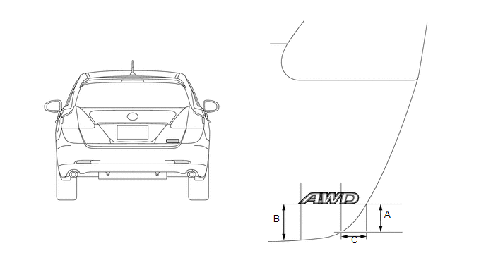 Standard Measurement
|
Dimension |
Measurement |
|---|---|
|
A |
41.6 mm (1.6378 in.) |
|
B |
52.3 mm (2.0591 in.) |
|
C |
37.6 mm (1.4803 in.) |
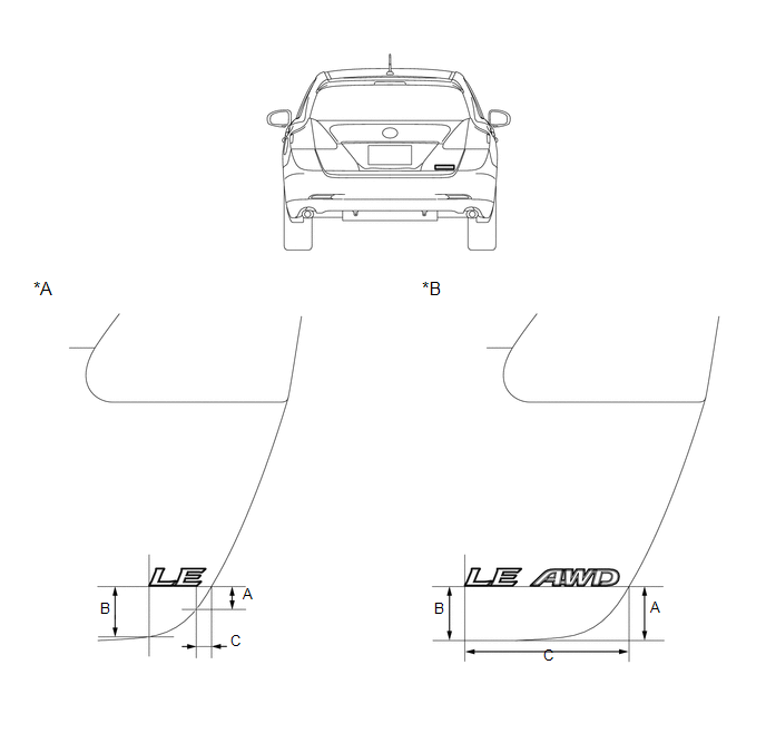
4. INSTALL NO. 4 LUGGAGE COMPARTMENT DOOR PLATE (w/ Grade Mark)
(a) Clean the vehicle body surface.
(1) Using a heat light, heat the vehicle body surface.
(2) Remove any double-sided tape from the vehicle body.
(3) Wipe off any tape adhesive residue with cleaner.
(b) Clean the name plate (if reusing the name plate).
(1) Using a heat light, heat the door plate.
(2) Remove the double-sided tape from the door plate.
(3) Wipe off any tape adhesive residue with cleaner.
(4) Apply new double-sided tape to the door plate.
(c) Install the No. 4 luggage compartment door plate.
(1) Using a heat light, heat the vehicle body and the new No. 4 luggage compartment door plate.
(2) Remove the release paper from the No. 4 luggage compartment door plate.
HINT:
After removing the release paper, keep the exposed adhesive free from foreign matter.
(3) Install the No. 4 luggage compartment door plate as shown in the illustration.
for LE:
 Standard Measurement
|
Dimension |
Measurement |
|
|---|---|---|
|
for 2WD |
for AWD |
|
|
A |
32.1 mm (1.2638 in.) |
52.6 mm (2.0709 in.) |
|
B |
51.5 mm (2.0276 in.) |
53.0 mm (2.0866 in.) |
|
C |
23.4 mm (0.9213 in.) |
169.9 mm (6.6890 in.) |
|
*A |
for 2WD |
*B |
for AWD |
for XLE:
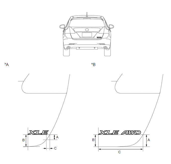 Standard Measurement
|
Dimension |
Measurement |
|
|---|---|---|
|
for 2WD |
for AWD |
|
|
A |
30.5 mm (1.2008 in.) |
52.6 mm (2.0709 in.) |
|
B |
53.0 mm (2.0866 in.) |
52.8 mm (2.0787 in.) |
|
C |
21.6 mm (0.8504 in.) |
193.2 mm (7.6063 in.) |
|
*A |
for 2WD |
*B |
for AWD |
for LIMITED:
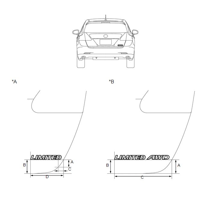 Standard Measurement
|
Dimension |
Measurement |
|
|---|---|---|
|
for 2WD |
for AWD |
|
|
A |
32.5 mm (1.2795 in.) |
52.9 mm (2.0827 in.) |
|
B |
52.9 mm (2.0827 in.) |
52.6 mm (2.0709 in.) |
|
C |
24.0 mm (0.9449 in.) |
221.7 mm (8.7283 in.) |
|
D |
124.5 mm (4.9016 in.) |
- |
|
*A |
for 2WD |
*B |
for AWD |
5. INSTALL HOOD EMBLEM
(a) Clean the vehicle body surface.
(1) Using a heat light, heat the vehicle body surface.
(2) Remove any double-sided tape from the vehicle body.
(3) Wipe off any tape adhesive residue with cleaner.
(b) Clean the name plate (if reusing the name plate).
(1) Using a heat light, heat the name plate.
(2) Remove the double-sided tape from the name plate.
(3) Wipe off any tape adhesive residue with cleaner.
(4) Apply new double-sided tape to the name plate.
(c) Install the hood emblem.
(1) Using a heat light, heat the vehicle body and the hood emblem.
(2) Remove the release paper from the hood emblem.
HINT:
After removing the release paper, keep the exposed adhesive free from foreign matter.
(3) Install the hood emblem as shown in the illustration.
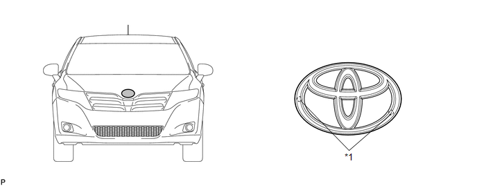 Text in Illustration
|
*1 |
Location Pin |
- |
- |
 Removal
REMOVAL
CAUTION / NOTICE / HINT
HINT:
When installing new name plates and emblem, heat the vehicle body, name plates
and emblem using a heat light.
Heating Temperature
Item
...
 Radiator Grille
Components
COMPONENTS
ILLUSTRATION
Removal
REMOVAL
PROCEDURE
1. REMOVE COOL AIR INTAKE DUCT SEAL
2. REMOVE RADIATOR GRILLE
(a) Put protective tape around the radiator grill ...
Other materials about Toyota Venza:
Check CAN Bus Line for Short to +B
DESCRIPTION
There may be a short circuit between the CAN bus main wire and +B when no resistance
exists between terminals 6 (CANH) and 16 (BAT) or 14 (CANL) and 16 (BAT) of the
DLC3.
Symptom
Trouble Area
No resistan ...
Power Mirrors do not Return to Memorized Position
SYSTEM DESCRIPTION
If either the M1 or M2 seat memory switch is pressed, the outer mirror control
ECU assembly (driver door) detects the seat memory switch status and sends the switch
signal to the main body ECU (driver side junction block assembly) via C ...
Inspection
INSPECTION
PROCEDURE
1. INSPECT COMPRESSOR WITH PULLEY (SOLENOID VALVE)
(a) Measure the resistance according to the value(s) in the table below.
Standard Resistance:
Tester Connection
Condition
...

0.1348