Toyota Venza: Removal
REMOVAL
PROCEDURE
1. DISCONNECT CABLE FROM NEGATIVE BATTERY TERMINAL
NOTICE:
When disconnecting the cable, some systems need to be initialized after the cable
is reconnected (See page .gif) ).
).
2. REMOVE REAR DOOR INSIDE HANDLE BEZEL PLUG
3. REMOVE REAR POWER WINDOW REGULATOR SWITCH ASSEMBLY WITH REAR DOOR ARMREST BASE PANEL
4. REMOVE REAR DOOR TRIM BOARD SUB-ASSEMBLY
5. REMOVE REAR DOOR INSIDE HANDLE SUB-ASSEMBLY
6. REMOVE REAR DOOR FRAME GARNISH
7. REMOVE REAR DOOR SERVICE HOLE COVER
8. REMOVE REAR DOOR CHECK ASSEMBLY
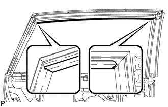
9. REMOVE REAR DOOR WEATHERSTRIP
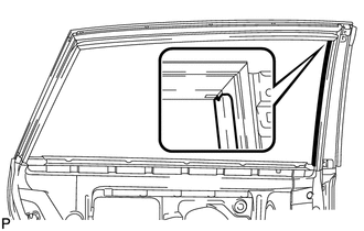
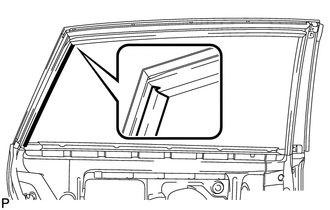
10. REMOVE REAR DOOR GLASS RUN
11. REMOVE REAR DOOR WINDOW DIVISION BAR SUB-ASSEMBLY
12. REMOVE REAR DOOR GLASS SUB-ASSEMBLY
13. REMOVE REAR DOOR OUTSIDE STRIPE
(a) Using a heat light, heat the rear door outside stripe and vehicle body.
Heating Temperature|
Item |
Temperature |
|---|---|
|
Vehicle Body |
40 to 60°C (104 to 140°F) |
NOTICE:
Do not heat the vehicle body excessively.
|
(b) Pull back on one of the ends of the rear door outside stripe to remove it. HINT: When pulling on the tape, pull it parallel to the body. |
|
14. REMOVE REAR DOOR LOWER OUTSIDE STRIPE
(a) Using a heat light, heat the rear door lower outside stripe and vehicle body.
Heating Temperature|
Item |
Temperature |
|---|---|
|
Vehicle Body |
40 to 60°C (104 to 140°F) |
NOTICE:
Do not heat the vehicle body excessively.
|
(b) Pull back on one of the ends of the rear door lower outside stripe to remove it. HINT: When pulling on the tape, pull it parallel to the body. |
|
15. REMOVE NO. 2 BLACK OUT TAPE
(a) Using a heat light, heat the No. 2 black out tape and vehicle body.
Heating Temperature|
Item |
Temperature |
|---|---|
|
Vehicle Body |
40 to 60°C (104 to 140°F) |
NOTICE:
Do not heat the vehicle body excessively.
|
(b) Pull back on one of the ends of the No. 2 black out tape to remove it. HINT: When pulling on the tape, pull it parallel to the body. |
|
 Components
COMPONENTS
ILLUSTRATION
ILLUSTRATION
ILLUSTRATION
...
 Installation
INSTALLATION
PROCEDURE
1. REPAIR INSTRUCTION
2. INSTALL REAR DOOR LOWER OUTSIDE STRIPE
(a) Refer to the illustration to position the rear door lower outside stripe.
Standard Measurement
...
Other materials about Toyota Venza:
Open in Driver Side Electrical Antenna Circuit (B27A1)
DESCRIPTION
The certification ECU (smart key ECU assembly) generates a request signal and
sends it to the electrical key oscillator built into the front door outside handle
assembly (for driver side) at 0.25-second intervals. To detect a key near the driv ...
Evaporative Emission Control System Pressure Sensor Range / Performance (P0451-P0453)
DTC SUMMARY
DTC No.
Monitoring Item
Malfunction Detection Condition
Trouble Area
Detection Timing
Detection Logic
P0451
Canister pressure sensor abnormal voltage flu ...
Room Temperature Sensor
Components
COMPONENTS
ILLUSTRATION
Removal
REMOVAL
PROCEDURE
1. DISCONNECT CABLE FROM NEGATIVE BATTERY TERMINAL
NOTICE:
When disconnecting the cable, some systems need to be initialized after the cable
is reconnected (See page ).
2. REMOVE FR ...

0.1336