Toyota Venza: Inspection
INSPECTION
CAUTION / NOTICE / HINT
NOTICE:
Ensure that fingers or articles of clothing do not get caught in moving parts when performing this test.
PROCEDURE
1. INSPECT WINDSHIELD WIPER MOTOR ASSEMBLY
|
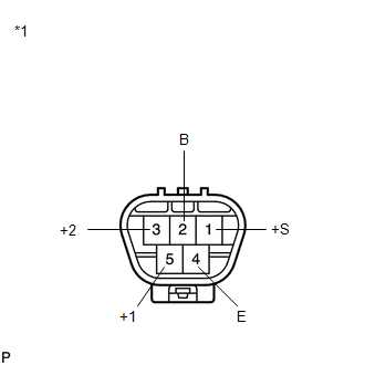
(a) Check the LO operation. (1) Connect a battery positive (+) lead to terminal 5 (+1) and a negative (-) lead to terminal 4 (E), and check that the motor operates at low speed (LO). OK: Motor operates at low speed (LO). Text in Illustration
|
|
(b) Check the HI operation.
(1) Connect a battery positive (+) lead to terminal 3 (+2) and a negative (-) lead to terminal 4 (E), and check that the motor operates at high speed (HI).
OK:
Motor operates at high speed (HI).
(c) Check the automatic stop (park) operation.
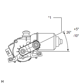
(1) Connect a battery positive (+) lead to terminal 5 (+1) and a negative (-) lead to terminal 4 (E). With the motor operating at low speed (LO), disconnect terminal 5 (+1) to stop the wiper motor operation at any position other than the matchmark.
(2) Using SST, connect terminals 1 (+S) and 5 (+1). Then connect a battery positive (+) lead to terminal 2 (B) and a negative (-) lead to terminal 4 (E) to restart the motor operation at low speed (LO).
SST: 09843-18040
|
(3) Check that the motor stops automatically at the automatic stop (park) position. OK: Motor stops automatically at the position. If the result is not as specified, replace the windshield wiper motor assembly. Text in Illustration
|
|
 On-vehicle Inspection
ON-VEHICLE INSPECTION
PROCEDURE
1. INSPECT WINDSHIELD WIPER MOTOR ASSEMBLY
(a) for RH Side
(1) Operate the windshield wiper motor assembly.
...
 Removal
REMOVAL
PROCEDURE
1. REMOVE FRONT WIPER ARM HEAD CAP
(a) Using a screwdriver, remove the 2 front wiper arm head caps as shown
in the illustration.
Text in Illustration
...
Other materials about Toyota Venza:
Cruise SET Indicator Light Circuit
DESCRIPTION
The ECM detects a cruise control switch signal and sends it to the combination
meter assembly through CAN. Then the SET indicator light comes on.
The SET indicator light circuit uses CAN for communication. If there
is a malfunct ...
Rear Power Window RH Auto Up / Down Function does not Operate with Rear Power
Window Switch RH
DESCRIPTION
If the manual up/down function can be performed but the auto up/down function
cannot, the fail-safe mode may be functioning.
If the power window initialization (See page
) has not been performed, the auto up/down function
will not operate.
...
Removal
REMOVAL
PROCEDURE
1. DISCONNECT CABLE FROM NEGATIVE BATTERY TERMINAL
CAUTION:
Wait at least 90 seconds after disconnecting the cable from the negative (-)
battery terminal to disable the SRS system.
NOTICE:
When disconnecting the cable, some systems ne ...

0.1522