Toyota Venza: Removal
REMOVAL
PROCEDURE
1. REMOVE REAR WHEELS
2. REMOVE REAR STABILIZER LINK ASSEMBLY LH
|
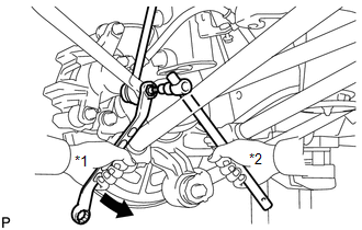
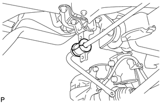
(a) Remove the nut and separate the rear stabilizer link assembly LH from the rear stabilizer bar. Text in Illustration
HINT: If the ball joint turns together with the nut, use a hexagon wrench (5 mm) to hold the stud bolt. |
|
|
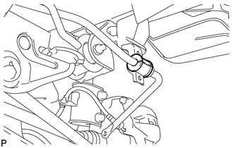
(b) Remove the nut and the rear stabilizer link assembly LH from the rear shock absorber with coil spring LH. Text in Illustration
HINT: If the ball joint turns together with the nut, use a hexagon wrench (5 mm) to hold the stud bolt. |
|
.png)
3. REMOVE REAR STABILIZER LINK ASSEMBLY RH
HINT:
Perform the same procedure as the LH side.
4. REMOVE NO. 1 FLOOR UNDER COVER
.gif)
5. REMOVE REAR LOWER SUSPENSION BRACE (for LH Side)
|
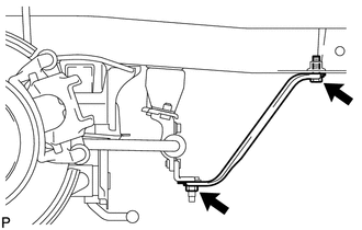
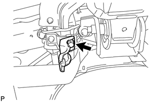
(a) Remove the bolt, the nut and the rear lower suspension brace (LH side). |
|
6. REMOVE REAR LOWER SUSPENSION BRACE (for RH Side)
HINT:
Perform the same procedure as the LH side.
7. REMOVE REAR STABILIZER BAR BRACKET LH (for Rear Side)
|
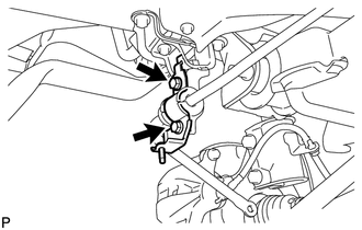
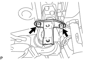
(a) Remove the 2 bolts and the rear stabilizer bar bracket LH (rear side). |
|
8. REMOVE REAR STABILIZER BAR BRACKET RH (for Rear Side)
|
(a) Remove the 2 bolts and the rear stabilizer bar bracket RH (rear side). |
|
9. REMOVE REAR STABILIZER BUSHING (for LH Side)
|
(a) Remove the rear stabilizer bushing (LH side). |
|
10. REMOVE REAR STABILIZER BUSHING (for RH Side)
|
(a) Remove the rear stabilizer bushing (RH side). |
|
11. REMOVE REAR STABILIZER BAR BRACKET LH (for Front Side)
|
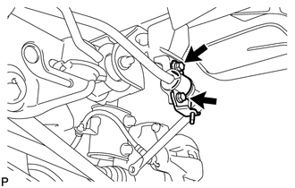
(a) Remove the bolt and the rear stabilizer bar bracket LH (front side). |
|
12. REMOVE REAR STABILIZER BAR BRACKET RH (for Front Side)
|
(a) Remove the 2 bolts and the rear stabilizer bar bracket RH (front side). |
|
 Inspection
INSPECTION
PROCEDURE
1. INSPECT REAR STABILIZER LINK ASSEMBLY
(a) Move the ball joint stud back and forth 5 times before installing
the nut as shown in the illustration.
...
 Installation
INSTALLATION
PROCEDURE
1. TEMPORARILY INSTALL REAR STABILIZER BAR BRACKET LH (for Front Side)
(a) Temporarily install the rear stabilizer bar bracket LH (front side)
with the bolt.
...
Other materials about Toyota Venza:
Removal
REMOVAL
PROCEDURE
1. DISCONNECT CABLE FROM NEGATIVE BATTERY TERMINAL
CAUTION:
Wait at least 90 seconds after disconnecting the cable from the negative (-)
battery terminal to disable the SRS system.
NOTICE:
When disconnecting the cable, some systems ne ...
P/W Master Switch Communication Stop (B1206)
DESCRIPTION
This DTC is stored when LIN communication between the multiplex network master
switch assembly and main body ECU (driver side junction block assembly) stops for
more than 10 seconds.
DTC No.
DTC Detection Condition
...
Installation
INSTALLATION
CAUTION / NOTICE / HINT
HINT:
Perform "Inspection After Repair" after replacing the engine assembly (See page
).
PROCEDURE
1. INSTALL ENGINE HANGERS
2. REMOVE ENGINE STAND
(a) Remove the engine stand.
3. INSTALL ENGINE WIRE
...

0.1367