Toyota Venza: P/W Master Switch Communication Stop (B1206)
DESCRIPTION
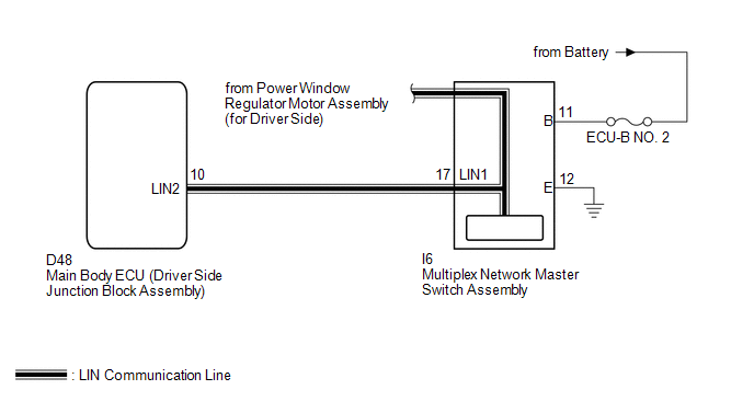
This DTC is stored when LIN communication between the multiplex network master switch assembly and main body ECU (driver side junction block assembly) stops for more than 10 seconds.
|
DTC No. |
DTC Detection Condition |
Trouble Area |
|---|---|---|
|
B1206 |
No communication between the multiplex network master switch assembly and main body ECU (driver side junction block assembly) for more than 10 seconds. |
|
WIRING DIAGRAM
CAUTION / NOTICE / HINT
NOTICE:
When using the Techstream to troubleshoot with the ignition switch off:
Connect the Techstream to the DLC3, and turn the courtesy switch on and off at 1.5-second intervals until communication between the Techstream and vehicle begins.
PROCEDURE
|
1. |
CHECK HARNESS AND CONNECTOR (MULTIPLEX NETWORK MASTER SWITCH - BATTERY AND BODY GROUND) |
|
(a) Disconnect the I6 switch connector. |
|
(b) Measure the resistance and voltage according to the value(s) in the table below.
Standard Resistance:
|
Tester Connection |
Condition |
Specified Condition |
|---|---|---|
|
I6-12 (E) - Body ground |
Always |
Below 1 Ω |
Standard Voltage:
|
Tester Connection |
Condition |
Specified Condition |
|---|---|---|
|
I6-11 (B) - Body ground |
Always |
11 to 14 V |
|
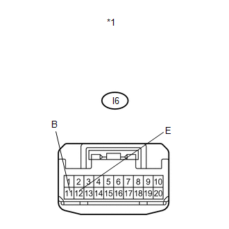
*1 |
Front view of wire harness connector (to Multiplex Network Master Switch Assembly) |
| NG | .gif) |
REPAIR OR REPLACE HARNESS OR CONNECTOR |
|
.gif)
|
2. |
CHECK HARNESS AND CONNECTOR (MAIN BODY ECU - MULTIPLEX NETWORK MASTER SWITCH) |
|
(a) Disconnect the D48 ECU connector. |
|
(b) Measure the resistance according to the value(s) in the table below.
Standard Resistance:
|
Tester Connection |
Condition |
Specified Condition |
|---|---|---|
|
D48-10 (LIN2) - I6-17 (LIN1) |
Always |
Below 1 Ω |
|
I6-17 (LIN1) - Body ground |
Always |
10 kΩ or higher |
|
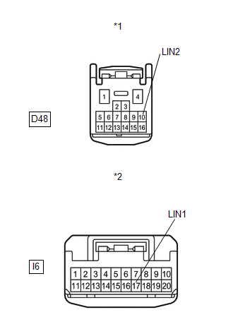
*1 |
Front view of wire harness connector (to Main Body ECU (Driver Side Junction Block Assembly)) |
|
*2 |
Front view of wire harness connector (to Multiplex Network Master Switch Assembly) |
| NG | |
REPAIR OR REPLACE HARNESS OR CONNECTOR |
|
|
3. |
REPLACE MULTIPLEX NETWORK MASTER SWITCH ASSEMBLY |
(a) Replace the multiplex network master switch assembly (See page
.gif) ).
).
|
|
4. |
CHECK DTC OUTPUT |
(a) Clear the DTC (See page ).
(b) Recheck for DTCs.
OK:
DTC B1206 is not output.
| OK | |
END (MULTIPLEX NETWORK MASTER SWITCH ASSEMBLY WAS DEFECTIVE) |
| NG | |
REPLACE MAIN BODY ECU (DRIVER SIDE JUNCTION BLOCK ASSEMBLY) |
 Lost Communication with AFS LIN (B124D)
DESCRIPTION
Refer to DTC B124D (Lighting system) (See page
).
DTC No.
DTC Detection Condition
Trouble Area
B124D
Malfunctions in LIN co ...

Other materials about Toyota Venza:
Transmission Fluid Temperature Sensor "A" Performance (P0711)
DESCRIPTION
The Automatic Transmission Fluid (ATF) temperature sensor converts the fluid
temperature into a resistance value for use by the TCM.
The TCM applies a voltage to the temperature sensor through terminal THO1 of
the TCM.
The sensor resistance ...
Programming HomeLink® (for U.S.A. owners)
To ensure correct programming into the HomeLink®, install a new battery in
the hand-held transmitter prior to programming. Failure to install a new battery
into the hand-held transmitter will affect both the range and accuracy of the HomeLink®
in your ...
Diagnostic Trouble Code Chart
DIAGNOSTIC TROUBLE CODE CHART
HINT:
If a trouble code is displayed during the DTC check, inspect the trouble areas
listed below for that code. For details of the code, refer to the following "See
page".
Power back door system
DTC C ...

0.1429