Toyota Venza: Installation
INSTALLATION
CAUTION / NOTICE / HINT
HINT:
Perform "Inspection After Repair" after replacing the engine assembly (See page
.gif) ).
).
PROCEDURE
1. INSTALL ENGINE HANGERS
2. REMOVE ENGINE STAND
(a) Remove the engine stand.
3. INSTALL ENGINE WIRE
(a) Install the engine wire.
4. INSTALL DRIVE PLATE AND RING GEAR SUB-ASSEMBLY
5. INSTALL REAR ENGINE MOUNTING BRACKET (for AWD)
|
(a) Install the rear engine mounting bracket with the 3 bolts. Torque: 64 N·m {650 kgf·cm, 47 ft·lbf} |
|
.png)
6. INSTALL DRIVE SHAFT BEARING BRACKET (for 2WD)
|
(a) Install the drive shaft bearing bracket with the 3 bolts. Torque: 64 N·m {649 kgf·cm, 47 ft·lbf} |
|
7. INSTALL ENGINE MOUNTING BRACKET RH
|
(a) Install the engine mounting bracket RH with the 3 bolts. Torque: 54 N·m {551 kgf·cm, 40 ft·lbf} |
|
.png)
8. INSTALL AUTOMATIC TRANSAXLE ASSEMBLY (for 2WD)
9. INSTALL AUTOMATIC TRANSAXLE ASSEMBLY (for AWD)
10. INSTALL TRANSFER STIFFENER PLATE RH (for AWD)
|
(a) Temporarily install the transfer stiffener plate RH. |
|
(b) Tighten the transfer stiffener plate RH with the 4 bolts to the transfer and rear engine mounting bracket.
Torque:
Bolt A :
34 N·m {347 kgf·cm, 25 ft·lbf}
Bolt B :
78 N·m {795 kgf·cm, 58 ft·lbf}
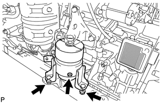
11. TEMPORARILY TIGHTEN FRONT ENGINE MOUNTING INSULATOR ASSEMBLY
|
(a) Temporarily install the front engine mounting insulator assembly with the 3 nuts. HINT: Perform this procedure only when replacement of the engine mounting insulator is necessary. |
|
.png)
12. TEMPORARILY TIGHTEN ENGINE MOUNTING INSULATOR LH
|
(a) Temporarily install the engine mounting insulator LH with the 3 nuts. HINT: Perform this procedure only when replacement of the engine mounting insulator is necessary. |
|
.png)
13. TEMPORARILY TIGHTEN ENGINE MOUNTING INSULATOR RH
|
(a) Temporarily install the engine mounting insulator RH with the 3 nuts. HINT: Perform this procedure only when replacement of the engine mounting insulator is necessary. |
|
.png)
14. TEMPORARILY TIGHTEN REAR ENGINE MOUNTING INSULATOR ASSEMBLY (for AWD)
|
(a) Temporarily install the rear engine mounting insulator with the 2 nuts. HINT: Perform this procedure only when replacement of the engine mounting insulator is necessary. |
|
.png)
15. INSTALL FRONT FRAME ASSEMBLY
(a) Set the engine assembly with transaxle to the front frame assembly.
|
(b) Install the engine mounting insulators RH and LH with the 2 nuts. Torque: 95 N·m {968 kgf·cm, 70 ft·lbf} |
|
.png)
|
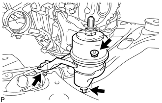
(c) Install the front engine mounting insulator with the bolt. Torque: 87 N·m {887 kgf·cm, 64 ft·lbf} |
|
.png)
|
(d) Connect the 2 clamps with the engine wire. |
|
.png)
16. INSTALL REAR ENGINE MOUNTING INSULATOR ASSEMBLY (for AWD)
|
(a) Install the rear engine mounting insulator assembly with the 2 bolts to the engine mounting bracket. Torque: 75 N·m {764 kgf·cm, 55 ft·lbf} |
|
.png)
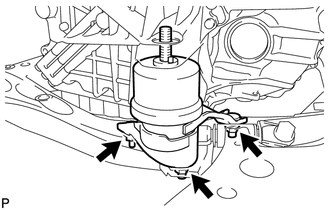
17. FULLY TIGHTEN FRONT ENGINE MOUNTING INSULATOR ASSEMBLY
|
(a) Fully tighten the front engine mounting insulator with the 3 nuts. Torque: 52 N·m {530 kgf·cm, 38 ft·lbf} |
|
(b) Install the hole plug.
HINT:
Perform this procedure only when replacement of the engine mounting insulator is necessary.
18. FULLY TIGHTEN ENGINE MOUNTING INSULATOR LH
|
(a) Fully tighten the engine mounting insulator LH with the 3 nuts. Torque: 87 N·m {887 kgf·cm, 64 ft·lbf} |
|
(b) Install the 2 hole plugs.
HINT:
Perform this procedure only when replacement of the engine mounting insulator is necessary.
19. FULLY TIGHTEN ENGINE MOUNTING INSULATOR RH
|
(a) Fully tighten the engine mounting insulator RH with the 3 nuts. Torque: 87 N·m {887 kgf·cm, 64 ft·lbf} |
|
(b) Install the 2 hole plugs.
HINT:
Perform this procedure only when replacement of the engine mounting insulator is necessary.
20. FULLY TIGHTEN REAR ENGINE MOUNTING INSULATOR ASSEMBLY (for AWD)
|
(a) Fully tighten the rear engine mounting insulator with the 2 nuts. Torque: 52 N·m {530 kgf·cm, 38 ft·lbf} |
|
(b) Install the 2 hole plugs.
HINT:
Perform this procedure only when replacement of the engine mounting insulator is necessary.
21. INSTALL STEERING LINK ASSEMBLY (for AWD)
22. INSTALL FRONT STABILIZER BAR (for AWD)
23. INSTALL NO. 1 FRONT STABILIZER BRACKET LH (for AWD)
24. INSTALL NO. 1 FRONT STABILIZER BRACKET RH (for AWD)
HINT:
Use the same procedure described for the LH side.
25. INSTALL STARTER ASSEMBLY
26. INSTALL COMPRESSOR ASSEMBLY WITH PULLEY
27. INSTALL GENERATOR ASSEMBLY
28. INSTALL V-RIBBED BELT
29. REMOVE ENGINE HANGERS
30. INSTALL ENGINE ASSEMBLY WITH TRANSAXLE
(a) Set the engine assembly with transaxle on the engine lifter.
(b) Install the engine assembly to the vehicle.
|
(c) Install the frame side rail plates RH and LH with the 4 bolts and 2 nuts. Torque: A : 85 N·m {866 kgf·cm, 62 ft·lbf} B : 32 N·m {326 kgf·cm, 24 ft·lbf} |
|
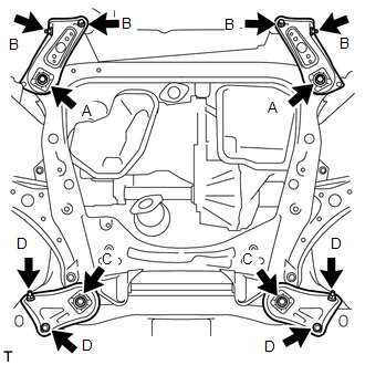
(d) Install the front suspension member rear braces RH and LH with the 4 bolts and 2 nuts.
Torque:
C :
85 N·m {866 kgf·cm, 62 ft·lbf}
D :
32 N·m {326 kgf·cm, 24 ft·lbf}
HINT:
Perform "Inspection After Repair" after replacing the engine assembly (See page
).
31. INSTALL DRIVE PLATE AND TORQUE CONVERTER SETTING BOLT
|
(a) Using SST, hold the crankshaft pulley. SST: 09213-54015 SST: 09330-00021 HINT: Part number of installation bolt for SST (crankshaft pulley holding tool): 91551-80650 (quantity: 2) |
|
.png)
|
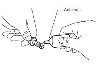
(b) Apply a few drops of adhesive to the first 2 or 3 threads of the 6 drive plate and torque converter setting bolts. Adhesive: Toyota Genuine Adhesive 1324, Three Bond 1324 or equivalent |
|
|
(c) Install the 6 drive plate and torque converter clutch setting bolts. Torque: 41 N·m {418 kgf·cm, 30 ft·lbf} NOTICE: Install the black colored bolt first, and then the 5 silver colored bolts. |
|
.png)
32. INSTALL FLYWHEEL HOUSING UNDER COVER
|
(a) Install the flywheel housing under cover. |
|
.png)
33. INSTALL FRONT FLOOR BRACE
|
(a) Install the front floor brace with the 4 nuts. Torque: 11 N·m {112 kgf·cm, 8 ft·lbf} |
|
.png)
34. INSTALL FRONT DRIVE SHAFT HOLE SNAP RING (for LH Side)
35. INSTALL FRONT DRIVE SHAFT ASSEMBLY LH
36. INSTALL FRONT DRIVE SHAFT ASSEMBLY RH (for 2WD)
37. INSTALL FRONT DRIVE SHAFT ASSEMBLY RH (for AWD)
38. INSTALL FRONT AXLE ASSEMBLY LH
39. INSTALL FRONT AXLE ASSEMBLY RH
HINT:
Use the same procedure described for the LH side.
40. INSTALL FRONT LOWER SUSPENSION ARM LH
41. INSTALL FRONT LOWER SUSPENSION ARM RH
HINT:
Use the same procedure described for the LH side.
42. INSTALL FRONT STABILIZER LINK ASSEMBLY LH
43. INSTALL FRONT STABILIZER LINK ASSEMBLY RH
HINT:
Use the same procedure described for the LH side.
44. INSTALL TIE ROD ASSEMBLY LH
45. INSTALL TIE ROD ASSEMBLY RH
HINT:
Use the same procedure described for the LH side.
46. INSTALL FRONT SPEED SENSOR LH
47. INSTALL FRONT SPEED SENSOR RH
HINT:
Use the same procedure described for the LH side.
48. INSTALL FRONT AXLE SHAFT NUT LH
49. INSTALL FRONT AXLE SHAFT NUT RH
HINT:
Use the same procedure described for the LH side.
50. INSTALL STEERING INTERMEDIATE SHAFT SUB-ASSEMBLY
51. TEMPORARILY TIGHTEN PROPELLER WITH CENTER BEARING SHAFT ASSEMBLY
52. FULLY TIGHTEN PROPELLER WITH CENTER BEARING SHAFT ASSEMBLY
53. INSTALL CENTER EXHAUST PIPE ASSEMBLY (for AWD)
54. INSTALL TAIL EXHAUST PIPE ASSEMBLY (for AWD)
55. INSTALL FRONT EXHAUST PIPE ASSEMBLY
56. CONNECT COOLER REFRIGERANT DISCHARGE HOSE
57. CONNECT SUCTION HOSE SUB-ASSEMBLY
58. CONNECT UNION TO CHECK VALVE HOSE
|
(a) Using pliers, grip the claws of the clip and slide the clip to connect the union to check valve hose to the intake air surge tank assembly. |
|
.png)
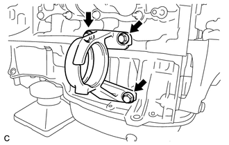
59. INSTALL ENGINE MOVING CONTROL ROD
|
(a) Temporarily install the engine moving control rod with the 4 bolts. |
|
.png)
|
(b) Temporarily install the No. 2 engine mounting stay with the 2 bolts |
|
.png)
(c) Tighten the 6 bolts.
Torque:
38 N·m {387 kgf·cm, 28 ft·lbf}
60. CONNECT ENGINE WIRE
|
(a) Connect the connector to the ECM with the lock lever. |
|
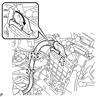
(b) Connect the engine wire with the 2 clamps.
|
(c) Install the ground cable with the bolt. Torque: 5.5 N·m {56 kgf·cm, 49 in·lbf} |
|
.png)
|
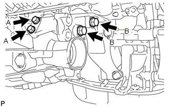
(d) Install the ground cable with the 2 bolts. Torque: Bolt A : 8.0 N·m {82 kgf·cm, 71 in·lbf} Bolt B : 12 N·m {122 kgf·cm, 9 ft·lbf} |
|
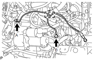
(e) Connect the ground cable clamp.
|
(f) Connect the positive (+) cable with the nut and 2 clamps. Torque: 9.8 N·m {100 kgf·cm, 87 in·lbf} |
|
.png)
|
(g) Install the ground cable with the bolt. Torque: 8.4 N·m {86 kgf·cm, 74 in·lbf} |
|
.png)
(h) Connect the 2 engine wire clamps.
|
(i) Connect the engine wire to the engine room relay block. Then, install it with the nut and 2 connectors. Torque: 8.0 N·m {85 kgf·cm, 74 in·lbf} |
|
.png)
(j) Install the No. 1 relay block cover.
61. CONNECT TRANSMISSION CONTROL CABLE ASSEMBLY
|
(a) Connect the transmission control cable assembly to the control shaft lever with a new clip and the nut. Torque: 13 N·m {130 kgf·cm, 9 ft·lbf} NOTICE: Before connecting the transmission control cable assembly, check that the park/neutral position switch and the shift lever are in N. |
|
.png)
62. CONNECT OUTLET NO. 1 OIL COOLER HOSE
|
(a) Connect the outlet No. 1 oil cooler hose. |
|
.png)
63. CONNECT INLET NO. 1 OIL COOLER HOSE
|
(a) Connect the inlet No. 1 oil cooler hose. |
|
.png)
64. CONNECT FUEL TUBE SUB-ASSEMBLY
|
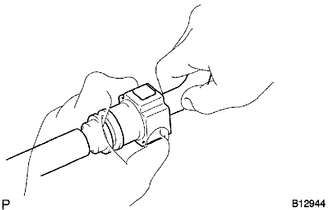
(a) Push in the fuel tube connector to the fuel pipe until the fuel tube makes a "click" sound. NOTICE:
|
|
|
(b) Install the No. 1 fuel pipe clamp. |
|
.png)
65. CONNECT OUTLET HEATER WATER HOSE
|
(a) Connect the outlet heater water hose. |
|
.png)
66. CONNECT INLET HEATER WATER HOSE
|
(a) Connect the inlet heater water hose. |
|
.png)
67. CONNECT NO. 1 RADIATOR HOSE
|
(a) Connect the No. 1 radiator hose. |
|
.png)
(b) Connect the wire harness clamp.
68. CONNECT NO. 2 RADIATOR HOSE
|
(a) Connect the No. 2 radiator outlet hose. |
|
.png)
69. INSTALL AIR CLEANER BRACKET
|
(a) Install the air cleaner bracket with the 2 bolts. Torque: 7.8 N·m {80 kgf·cm, 69 in·lbf} |
|
.png)
70. INSTALL AIR CLEANER CASE SUB-ASSEMBLY
|
(a) Install the air cleaner case sub-assembly with the 3 bolts. Torque: 5.0 N·m {51 kgf·cm, 44 in·lbf} |
|
.png)
(b) connect the wire harness clamp.
71. INSTALL AIR CLEANER FILTER ELEMENT SUB-ASSEMBLY
(a) Install the air cleaner filter element sub-assembly.
72. INSTALL AIR CLEANER CAP SUB-ASSEMBLY
73. INSTALL INLET AIR CLEANER ASSEMBLY
|
(a) Install the inlet air cleaner assembly with the 2 bolts. Torque: 5.0 N·m {51 kgf·cm, 44 in·lbf} |
|
.png)
74. INSTALL BATTERY
(a) Install the battery tray and battery.
|
(b) Install the battery clamp with the bolt and nut. Torque: Bolt A : 9.0 N·m {92 kgf·cm, 80 in·lbf} Nut B : 3.5 N·m {36 kgf·cm, 31 in·lbf} |
|
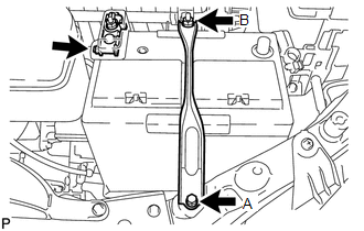
(c) Install the positive (+) battery terminal with the nut.
Torque:
6.4 N·m {65 kgf·cm, 57 in·lbf}
75. INSTALL OUTER COWL TOP PANEL SUB-ASSEMBLY
76. INSTALL WINDSHIELD WIPER MOTOR AND LINK ASSEMBLY
77. INSTALL COWL TOP VENTILATOR LOUVER SUB-ASSEMBLY
78. INSTALL FRONT FENDER TO COWL SIDE SEAL LH
79. INSTALL FRONT FENDER TO COWL SIDE SEAL RH
HINT:
Use the same procedure for the RH side and LH side.
80. INSTALL FRONT WIPER ARM AND BLADE ASSEMBLY LH
81. INSTALL FRONT WIPER ARM AND BLADE ASSEMBLY RH
82. INSTALL FRONT WIPER ARM HEAD CAP
83. INSTALL FRONT WHEELS
Torque:
103 N·m {1050 kgf·cm, 76 ft·lbf}
84. CONNECT CABLE TO NEGATIVE BATTERY TERMINAL
NOTICE:
When disconnecting the cable, some systems need to be initialized after the cable
is reconnected (See page ).
85. ADD ENGINE OIL
86. ADD ENGINE COOLANT
87. ADD AUTOMATIC TRANSAXLE FLUID (for 2WD)
HINT:
(See page )
88. ADD AUTOMATIC TRANSAXLE FLUID (for AWD)
HINT:
(See page )
89. ADD TRANSFER OIL (for AWD)
90. CHARGE REFRIGERANT
91. INSPECT FOR FUEL LEAK
92. INSPECT FOR OIL LEAK
93. INSPECT FOR COOLANT LEAK
94. INSPECT FOR EXHAUST GAS LEAK
95. INSPECT FOR REFRIGERANT LEAK
96. INSPECT AND ADJUST SHIFT LEVER POSITION (for 2WD)
HINT:
(See page )
97. INSPECT AND ADJUST SHIFT LEVER POSITION (for AWD)
HINT:
(See page )
98. INSPECT AND ADJUST FRONT WHEEL ALIGNMENT
HINT:
(See page )
99. INSPECT IGNITION TIMING
100. INSPECT ENGINE IDLE SPEED
101. INSPECT CO/HC
102. INSTALL FRONT FENDER APRON SEAL LH
|
(a) Install the front fender apron seal LH with the 2 bolts and clip. |
|
.png)
103. INSTALL FRONT FENDER APRON SEAL RH
|
(a) Install the front fender apron seal RH with the 2 bolts and clip. |
|
.png)
104. INSTALL FRONT FENDER LINER LH
105. INSTALL FRONT FENDER LINER RH
106. INSTALL NO. 2 ENGINE UNDER COVER
107. INSTALL NO. 1 ENGINE UNDER COVER
108. INSTALL NO. 1 ENGINE COVER SUB-ASSEMBLY
|
(a) Fit the 3 retainers and install the No. 1 engine cover sub-assembly. |
|
.png)
109. INSTALL COOL AIR INTAKE DUCT SEAL
|
(a) Install the cool air intake duct seal with the 12 clips. |
|
.png)
110. CHECK SPEED SENSOR SIGNAL
HINT:
(See page )
 Removal
REMOVAL
PROCEDURE
1. RECOVER REFRIGERANT FROM REFRIGERATION SYSTEM
2. DISCHARGE FUEL SYSTEM PRESSURE
3. PLACE FRONT WHEELS FACING STRAIGHT AHEAD
4. REMOVE FRONT WHEELS
5. DISCONNECT CABLE ...
 Engine Unit
...
Other materials about Toyota Venza:
Removal
REMOVAL
CAUTION / NOTICE / HINT
HINT:
Use the same procedure for the RH side and LH side.
The procedure listed below is for the LH side.
PROCEDURE
1. PRECAUTION
CAUTION:
Be sure to read Precaution thoroughly before servicing (See page
...
Precaution
PRECAUTION
1. PRECAUTION FOR DISCONNECTING THE BATTERY CABLE
NOTICE:
When disconnecting the cable from the negative (-) battery terminal, initialize
the following systems after the cable is reconnected:
System
See Procedure
...
Portable Player cannot be Operated Using In-vehicle Device or Track Information
is not Displayed on In-vehicle Device
PROCEDURE
1.
CHECK USING ANOTHER "Bluetooth" AUDIO COMPATIBLE VEHICLE OF SAME MODEL
(a) Check if track information is displayed normally on another "Bluetooth" audio
compatible vehicle of the same model.
...

0.1487