Toyota Venza: Removal
REMOVAL
CAUTION / NOTICE / HINT
HINT:
- Use the same procedure for the LH side and RH side.
- The following procedure is for the LH side.
PROCEDURE
1. REMOVE ENGINE ASSEMBLY WITH TRANSAXLE (for 2GR-FE)
HINT:
Refer to the procedure up to Remove Engine Assembly with Transaxle (See page
.gif) ).
).
2. REMOVE ENGINE ASSEMBLY WITH TRANSAXLE (for 1AR-FE)
HINT:
Refer to the procedure up to Remove Engine Assembly with Transaxle (See page
).
3. REMOVE FRONT NO. 1 STABILIZER BRACKET LH (for AWD)
4. REMOVE FRONT NO. 1 STABILIZER BRACKET RH (for AWD)
HINT:
Perform the same procedure as for the LH side.
5. REMOVE FRONT STABILIZER BAR WITH FRONT STABILIZER LINK ASSEMBLY (for AWD)
6. REMOVE STEERING LINK ASSEMBLY (for AWD)
7. REMOVE FRONT FRAME ASSEMBLY (for 2GR-FE)
8. SEPARATE REAR ENGINE MOUNTING INSULATOR ASSEMBLY (for 1AR-FE AWD)
9. REMOVE FRONT FRAME ASSEMBLY (for 1AR-FE)
10. REMOVE ENGINE MOUNTING INSULATOR LH (for 2GR-FE)
11. REMOVE ENGINE MOUNTING INSULATOR LH (for 1AR-FE)
12. REMOVE FRONT LOWER SUSPENSION ARM
|
(a) Remove the 3 bolts, nut and front lower suspension arm from the front frame assembly. |
|
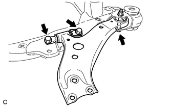
(b) Remove the front lower arm bushing stopper from the front lower suspension arm.
 Components
COMPONENTS
ILLUSTRATION
ILLUSTRATION
ILLUSTRATION
ILLUSTRATION
...
 Installation
INSTALLATION
CAUTION / NOTICE / HINT
HINT:
Use the same procedure for the LH side and RH side.
The following procedure is for the LH side.
PROCEDURE
1. INSTALL FRONT LOWER SUSPE ...
Other materials about Toyota Venza:
Removal
REMOVAL
CAUTION / NOTICE / HINT
HINT:
Use the same procedure for the RH side and LH side.
The procedure listed below is for the LH side.
PROCEDURE
1. REMOVE FRONT WHEEL
2. REMOVE FRONT AXLE SHAFT NUT
3. SEPARATE FRONT SPEED SENSOR
...
Repair
REPAIR
PROCEDURE
1. REPAIR INTAKE VALVE SEAT
NOTICE:
Repair the seat while checking the seating position.
Keep the lip free of foreign matter.
Take off the cutter gradually to make the intake valve seat smooth.
(a) Usin ...
Reassembly
REASSEMBLY
PROCEDURE
1. INSTALL GENERATOR ROTOR ASSEMBLY
(a) Place the drive end frame on the clutch pulley.
(b) Install the generator rotor assembly to the drive end frame.
2. INSTALL GENERATOR CL ...

0.1806