Toyota Venza: Components
COMPONENTS
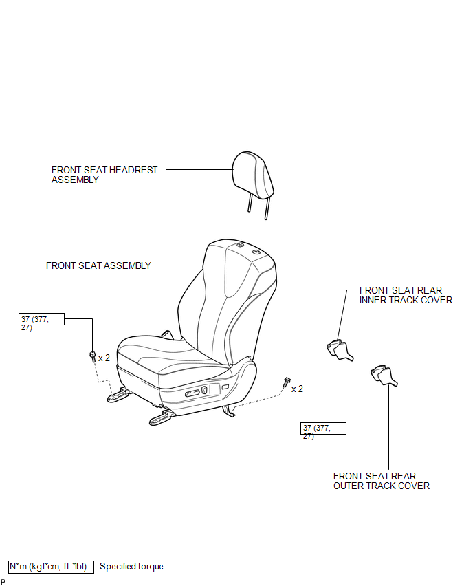
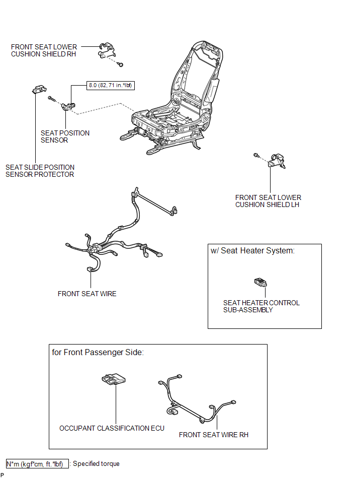
ILLUSTRATION
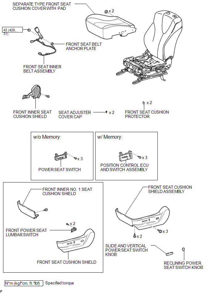
ILLUSTRATION
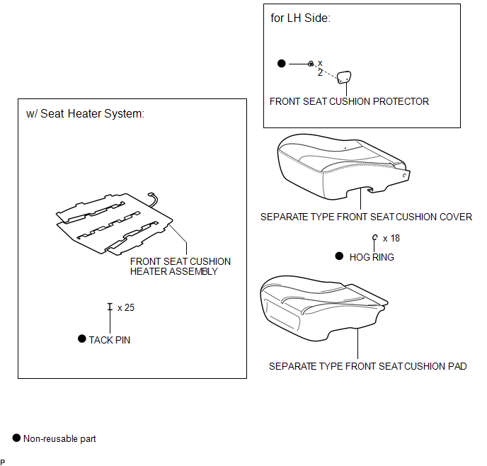
ILLUSTRATION
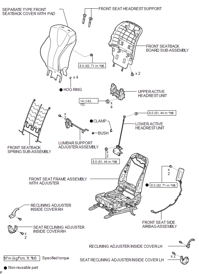
ILLUSTRATION
ILLUSTRATION
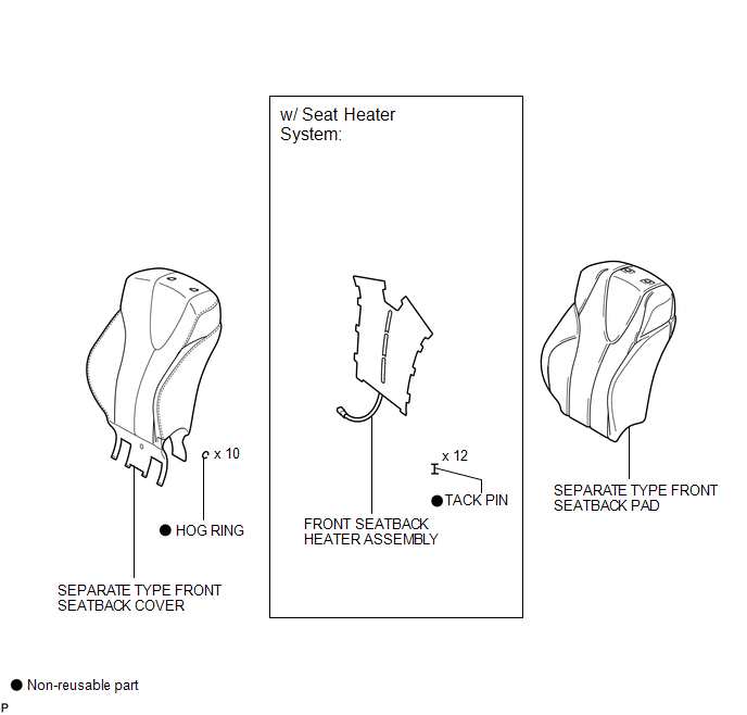
ILLUSTRATION

 Removal
REMOVAL
PROCEDURE
1. PRECAUTION
CAUTION:
Be sure to read Precaution thoroughly before servicing (See page
).
If the front seat side airbag assembly was deployed, replace the front ...
Other materials about Toyota Venza:
Power Seat Position is not Memorized
DESCRIPTION
The main body ECU (driver side junction block assembly) receives seat memory
switch signals from the outer mirror control ECU assembly LH via CAN communication.
If the seat memory SET switch is being pressed when one of the M1 or M2 switches
...
Operation Check
OPERATION CHECK
1. CHECK NAVIGATION SYSTEM NORMAL CONDITION
(a) If the symptom is applicable to any of the following, it is intended behavior,
and not a malfunction.
Symptom
Answer
A longer route than expected is cho ...
Illumination Circuit
DESCRIPTION
Power is supplied to the radio and display receiver assembly and steering pad
switch assembly illumination when the light control switch is in the tail or head
position.
WIRING DIAGRAM
CAUTION / NOTICE / HINT
NOTICE:
The vehicle ...

0.1605