Toyota Venza: Installation
INSTALLATION
CAUTION / NOTICE / HINT
HINT:
- Use the same procedure for the LH side and RH side.
- The following procedure is for the LH side.
PROCEDURE
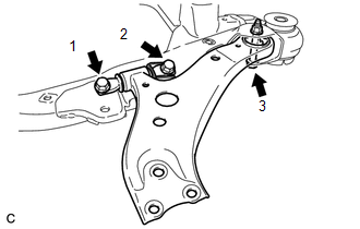
1. INSTALL FRONT LOWER SUSPENSION ARM
(a) Install the front lower arm bushing stopper to the front lower suspension arm.
(b) Temporarily tighten the front lower suspension arm to the front frame assembly with the 3 bolts and nut.
|
(c) Tighten the 3 bolts in the order shown in the illustration. Torque: Bolt 1, 2 : 200 N·m {2039 kgf·cm, 147 ft·lbf} Bolt 3 : 135 N·m {1377 kgf·cm, 100 ft·lbf} HINT: Start installing the bolts from the front of the vehicle. |
|
2. TEMPORARILY TIGHTEN ENGINE MOUNTING INSULATOR LH (for 2GR-FE)
.gif)
3. TEMPORARILY TIGHTEN ENGINE MOUNTING INSULATOR LH (for 1AR-FE)
4. INSTALL FRONT FRAME ASSEMBLY (for 2GR-FE)
5. INSTALL FRONT FRAME ASSEMBLY (for 1AR-FE)
6. INSTALL REAR ENGINE MOUNTING INSULATOR ASSEMBLY (for 1AR-FE AWD)
7. FULLY TIGHTEN ENGINE MOUNTING INSULATOR LH (for 2GR-FE)
8. FULLY TIGHTEN ENGINE MOUNTING INSULATOR LH (for 1AR-FE)
9. INSTALL STEERING LINK ASSEMBLY (for AWD)
10. INSTALL FRONT STABILIZER BAR WITH FRONT STABILIZER LINK ASSEMBLY (for AWD)
11. INSTALL FRONT NO. 1 STABILIZER BRACKET LH (for AWD)
12. INSTALL FRONT NO. 1 STABILIZER BRACKET RH (for AWD)
HINT:
Perform the same procedure as for the LH side.
13. INSTALL ENGINE ASSEMBLY WITH TRANSAXLE (for 2GR-FE)
HINT:
Refer to the procedure form Install Engine Assembly with Transaxle (See page
).
14. INSTALL ENGINE ASSEMBLY WITH TRANSAXLE (for 1AR-FE)
HINT:
Refer to the procedure form Install Engine Assembly with Transaxle (See page
).
 Removal
REMOVAL
CAUTION / NOTICE / HINT
HINT:
Use the same procedure for the LH side and RH side.
The following procedure is for the LH side.
PROCEDURE
1. REMOVE ENGINE ASSEMBLY WITH TR ...
 Front Lower Suspension Arm(when Using The Engine Support Bridge)
Components
COMPONENTS
ILLUSTRATION
Removal
REMOVAL
CAUTION / NOTICE / HINT
HINT:
Use the same procedure for the LH side and RH side.
The following procedure is for the LH side ...
Other materials about Toyota Venza:
USB Media Malfunction (B1585)
DESCRIPTION
This DTC is stored when a malfunction occurs in a connected device.
DTC No.
DTC Detection Condition
Trouble Area
B1585
When any of the following conditions is met:
A non m ...
Installation
INSTALLATION
PROCEDURE
1. INSTALL SPIRAL WITH SENSOR CABLE SUB-ASSEMBLY
(a) Install the spiral with sensor cable sub-assembly (See page
).
NOTICE:
Do not replace the spiral cable with the battery connected and the engine
switch on (IG).
...
Precaution
PRECAUTION
1. NOTICE FOR INITIALIZATION
CAUTION:
When disconnecting the cable from the negative (-) battery terminal, initialize
the following system after the cable is reconnected.
System Name
See Procedure
Back Do ...

0.1303