Toyota Venza: Components
COMPONENTS
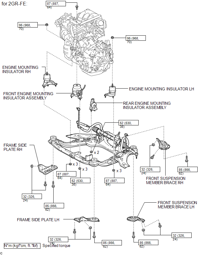
ILLUSTRATION
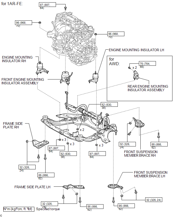
ILLUSTRATION
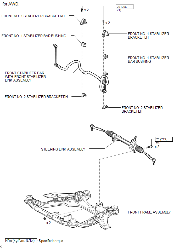
ILLUSTRATION
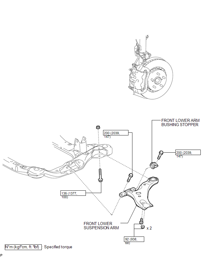
ILLUSTRATION

 Removal
REMOVAL
CAUTION / NOTICE / HINT
HINT:
Use the same procedure for the LH side and RH side.
The following procedure is for the LH side.
PROCEDURE
1. REMOVE ENGINE ASSEMBLY WITH TR ...
Other materials about Toyota Venza:
Inspection
INSPECTION
PROCEDURE
1. INSPECT REAR STABILIZER LINK ASSEMBLY
(a) Move the ball joint stud back and forth 5 times before installing
the nut as shown in the illustration.
(b) Using a torque wrenc ...
Removal
REMOVAL
PROCEDURE
1. DISCONNECT CABLE FROM NEGATIVE BATTERY TERMINAL
CAUTION:
Wait at least 90 seconds after disconnecting the cable from the negative (-)
battery terminal to disable the SRS system (See page
).
NOTICE:
When disconnecting the cable, s ...
Camshaft Position Sensor Circuit Malfunction (P0340,P0342,P0343)
DESCRIPTION
The camshaft position sensor (G signal sensor) for the intake camshaft consists
of a magnet and MRE (Magneto Resistance Element).
The camshaft has a timing rotor for the camshaft position sensor. When the camshaft
rotates, changes occur in th ...

0.1632