Toyota Venza: Terminals Of Ecu
TERMINALS OF ECU
1. CHECK ENGINE SWITCH
(a) Disconnect the D13 engine switch connector.

(b) Measure the resistance according to the value(s) in the table below.
HINT:
Measure the values on the wire harness side with connector disconnected.
|
Tester Connection |
Wiring Color |
Terminal Description |
Condition |
Specified Condition |
|---|---|---|---|---|
|
D13-8 (AGND) - Body ground |
V - Body ground |
Ground |
Always |
Below 1 Ω |
If the result is not as specified, there may be a malfunction in the wire harness.
(c) Reconnect the D13 engine switch connector.
(d) Measure the voltage according to the value(s) in the table below.
|
Tester Connection |
Wiring Color |
Terminal Description |
Condition |
Specified Condition |
|---|---|---|---|---|
|
D13-9 (TXCT) - D13-8 (AGND) |
GR - V |
Key code output signal |
|
Below 1 V |
|
D13-9 (TXCT) - D13-8 (AGND) |
GR - V |
Key code output signal |
|
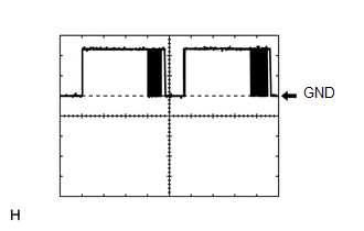
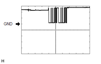
Pulse generation (See waveform 1) |
|
D13-10 (CODE) - D13-8 (AGND) |
LG - V |
Demodulated signal of key code data |
|
Below 1 V |
|
D13-10 (CODE) - D13-8 (AGND) |
LG - V |
Demodulated signal of key code data |
|
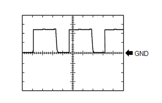
Pulse generation (See waveform 2) |
|
D13-14 (VC5) - D13-8 (AGND) |
R - V |
Power supply |
|
Below 1 V |
|
D13-14 (VC5) - D13-8 (AGND) |
R - V |
Power supply |
|
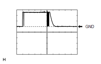
Pulse generation (See waveform 3) |
If the result is not as specified, the engine switch may have a malfunction.
(e) Inspect using an oscilloscope.
(1) Waveform 1 (Reference)
|
Item |
Content |
|---|---|
|
Tester Connection |
D13-9 (TXCT) - D13-8 (AGND) |
|
Tool Setting |
2 V/DIV., 50 ms./DIV. |
|
Condition |
|
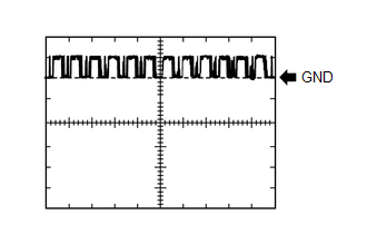
(2) Waveform 2 (Reference)
|
Item |
Content |
|---|---|
|
Tester Connection |
D13-10 (CODE) - D13-8 (AGND) |
|
Tool Setting |
2 V/DIV., 50 ms./DIV. |
|
Condition |
|
(3) Waveform 3 (Reference)
|
Item |
Content |
|---|---|
|
Tester Connection |
D13-14 (VC5) - D13-8 (AGND) |
|
Tool Setting |
2 V/DIV., 200 ms./DIV. |
|
Condition |
|
2. CHECK CERTIFICATION ECU (SMART KEY ECU ASSEMBLY)
(a) Disconnect the D25 certification ECU (smart key ECU assembly) connector.
(b) Measure the resistance and voltage according to the value(s) in the table below.
HINT:
Measure the values on the wire harness side with connector disconnected.
|
Tester Connection |
Wiring Color |
Terminal Description |
Condition |
Specified Condition |
|---|---|---|---|---|
|
D25-1 (+B) - D25-15 (E) |
G - B |
+B power supply |
Always |
11 to 14 V |
|
D25-15 (E) - Body ground |
B - Body ground |
Ground |
Always |
Below 1 Ω |
If the result is not as specified, there may be a malfunction in the wire harness.
(c) Reconnect the D25 certification ECU (smart key ECU assembly) connector.
(d) Measure the resistance and voltage according to the value(s) in the table below.
|
Tester Connection |
Wiring Color |
Terminal Description |
Condition |
Specified Condition |
|---|---|---|---|---|
|
D25-2 (INDS) - Body ground |
Y - Body ground |
Security indicator light signal |
Engine switch on (IG), security indicator light off |
Below 2 V |
|
D25-2 (INDS) - Body ground |
Y - Body ground |
Security indicator light signal |
Engine switch off, security indicator light blinks |
Pulse generation |
|
D25-12 (TXCT) - D25-36 (AGND) |
GR - V |
Engine switch TXCT output |
|
Below 1 V |
|
D25-12 (TXCT) - D25-36 (AGND) |
GR - V |
Engine switch TXCT output |
|
Pulse generation (See waveform 1) |
|
D25-13 (CODE) - D25-36 (AGND) |
LG - V |
Engine switch CODE input |
|
Below 1 V |
|
D25-13 (CODE) - D25-36 (AGND) |
LG - V |
Engine switch CODE input |
|
Pulse generation (See waveform 2) |
|
D25-16 (IG) - D25-15 (E) |
R - B |
Ignition power supply |
Engine switch off |
Below 1 V |
|
D25-16 (IG) - D25-15 (E) |
R - B |
Ignition power supply |
Engine switch on (IG) |
11 to 14 V |
|
D25-28 (VC5) - D25-36 (AGND) |
R - V |
Engine switch power supply |
|
Below 1 V |
|
D25-28 (VC5) - D25-36 (AGND) |
R - V |
Engine switch power supply |
|
Pulse generation (See waveform 3) |
|
D25-34 (EFII) - D25-15 (E) |
BR - B |
ECM input signal |
Engine switch off |
11 to 14 V |
|
D25-34 (EFII) - D25-15 (E) |
BR - B |
ECM input signal |
Within 3 seconds after the starter operates and initial combustion occurs, or within 3 seconds after engine switch first turned on (IG) after battery disconnected and connected |
Pulse generation (See waveform 4) |
|
D25-35 (EFIO) - D25-15 (E) |
G - B |
ECM output signal |
Engine switch off |
11 to 14 V |
|
D25-35 (EFIO) - D25-15 (E) |
G - B |
ECM output signal |
Engine switch on (IG) |
Pulse generation (See waveform 5) |
|
D25-36 (AGND) - Body ground |
V - Body ground |
Engine switch ground |
Always |
Below 1 Ω |
If the result is not as specified, the certification ECU (smart key ECU assembly) may have a malfunction.
(e) Inspect using an oscilloscope.
(1) Waveform 1 (Reference)
|
Item |
Content |
|---|---|
|
Tester Connection |
D25-12 (TXCT) - D25-36 (AGND) |
|
Tool Setting |
2 V/DIV., 50 ms./DIV. |
|
Condition |
|
(2) Waveform 2 (Reference)
|
Item |
Content |
|---|---|
|
Tester Connection |
D25-13 (CODE) - D25-36 (AGND) |
|
Tool Setting |
2 V/DIV., 50 ms./DIV. |
|
Condition |
|
(3) Waveform 3 (Reference)
|
Item |
Content |
|---|---|
|
Tester Connection |
D25-28 (VC5) - D25-36 (AGND) |
|
Tool Setting |
2 V/DIV., 200 ms./DIV. |
|
Condition |
|
(4) Waveform 4 (Reference)
|
Item |
Content |
|---|---|
|
Tester Connection |
D25-34 (EFII) - D25-15 (E) |
|
Tool Setting |
5 V/DIV., 500 ms/DIV. |
|
Condition |
Within 3 seconds after the starter operates and initial combustion occurs, or within 3 seconds after engine switch first turned on (IG) after battery disconnected and connected |
(5) Waveform 5 (Reference)
|
Item |
Content |
|---|---|
|
Tester Connection |
D25-35 (EFIO) - D25-15 (E) |
|
Tool Setting |
5 V/DIV., 100 ms./DIV. |
|
Condition |
Engine switch on (IG) |
3. CHECK STEERING LOCK ECU (STEERING LOCK ACTUATOR ASSEMBLY)
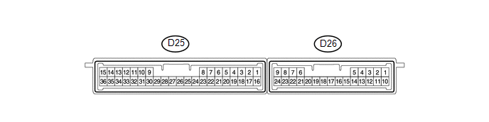
(a) Disconnect the D17 steering lock ECU (steering lock actuator assembly) connector.
.png)
(b) Measure the resistance and voltage according to the value(s) in the table below.
HINT:
Measure the values on the wire harness side with connector disconnected.
|
Tester Connection |
Wiring Color |
Terminal Description |
Condition |
Specified Condition |
|---|---|---|---|---|
|
D17-1 (GND) - Body ground |
W-B - Body ground |
Ground |
Always |
Below 1 Ω |
|
D17-6 (IG2) - Body ground |
LG - Body ground |
Ignition power supply |
Engine switch off |
Below 1 V |
|
D17-6 (IG2) - Body ground |
LG - Body ground |
Ignition power supply |
Engine switch on (IG) |
11 to 14 V |
|
D17-7 (B) - Body ground |
P - Body ground |
+B power supply |
Always |
11 to 14 V |
If the result is not as specified, there may be a malfunction in the wire harness.
4. CHECK ECM (for 2GR-FE)
(a) The values listed under "Specified Condition" are reference values. Because waterproof connectors are used for ECM, inspections cannot be performed with the connectors connected.
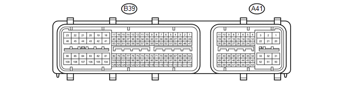
|
Tester Connection |
Wiring Color |
Terminal Description |
Condition |
Specified Condition |
|---|---|---|---|---|
|
B39-81 (E1) - Body ground |
W - Body ground |
Ground |
Always |
Below 1 Ω |
|
A41-29 (IMO) - B39-81 (E1) |
BR - W |
Certification ECU (smart key ECU assembly) output signal |
Engine switch off |
11 to 14 V |
|
A41-29 (IMO) - B39-81 (E1) |
BR - W |
Certification ECU (smart key ECU assembly) output signal |
Within 3 seconds after the starter operates and initial combustion occurs, or within 3 seconds after engine switch first turned on (IG) after battery disconnected and connected |
Pulse generation (See waveform 1) |
|
A41-40 (IMI) - B39-81 (E1) |
G - W |
Certification ECU (smart key ECU assembly) input signal |
Engine switch off |
11 to 14 V |
|
A41-40 (IMI) - B39-81 (E1) |
G - W |
Certification ECU (smart key ECU assembly) input signal |
Engine switch on (IG) |
Pulse generation (See waveform 2) |
(b) Waveform:
(1) Waveform 1 (Reference)
|
Item |
Content |
|---|---|
|
Tester Connection |
A41-29 (IMO) - B39-81 (E1) |
|
Tool Setting |
5 V/DIV., 500 ms./DIV. |
|
Condition |
Within 3 seconds after the starter operates and initial combustion occurs, or within 3 seconds after engine switch first turned on (IG) after battery disconnected and connected |
(2) Waveform 2 (Reference)
|
Item |
Content |
|---|---|
|
Tester Connection |
A41-40 (IMI) - B39-81 (E1) |
|
Tool Setting |
5 V/DIV., 100 ms./DIV. |
|
Condition |
Engine switch on (IG) |
5. CHECK ECM (for 1AR-FE)
(a) The values listed under "Specified Condition" are reference values. Because waterproof connectors are used for ECM, inspections cannot be performed with the connectors connected.
|
Tester Connection |
Wiring Color |
Terminal Description |
Condition |
Specified Condition |
|---|---|---|---|---|
|
B58-104 (E1) - Body ground |
BR - Body ground |
Ground |
Always |
Below 1 Ω |
|
A49-10 (IMO) - B58-104 (E1) |
BR - BR |
Certification ECU (smart key ECU assembly) output signal |
Engine switch off |
11 to 14 V |
|
A49-10 (IMO) - B58-104 (E1) |
BR - BR |
Certification ECU (smart key ECU assembly) output signal |
Within 3 seconds after the starter operates and initial combustion occurs, or within 3 seconds after engine switch first turned on (IG) after battery disconnected and connected |
Pulse generation (See waveform 1) |
|
A49-11 (IMI) - B58-104 (E1) |
G - BR |
Certification ECU (smart key ECU assembly) input signal |
Engine switch off |
Below 1 V |
|
A49-11 (IMI) - B58-104 (E1) |
G - BR |
Certification ECU (smart key ECU assembly) input signal |
Engine switch on (IG) |
Pulse generation (See waveform 2) |
(b) Waveform:
(1) Waveform 1 (Reference)
|
Item |
Content |
|---|---|
|
Tester Connection |
A49-10 (IMO) - B58-104 (E1) |
|
Tool Setting |
5 V/DIV., 500 ms./DIV. |
|
Condition |
Within 3 seconds after the starter operates and initial combustion occurs, or within 3 seconds after engine switch first turned on (IG) after battery disconnected and connected |
(2) Waveform 2 (Reference)
|
Item |
Content |
|---|---|
|
Tester Connection |
A49-11 (IMI) - B58-104 (E1) |
|
Tool Setting |
5 V/DIV., 100 ms./DIV. |
|
Condition |
Engine switch on (IG) |
6. CHECK POWER MANAGEMENT CONTROL ECU
(a) Disconnect the D43 power management control ECU connector.
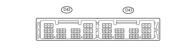
(b) Measure the resistance and voltage according to the value(s) in the table below.
HINT:
Measure the values on the wire harness side with connector disconnected.
|
Tester Connection |
Wiring Color |
Terminal Description |
Condition |
Specified Condition |
|---|---|---|---|---|
|
D43-1 (AM22) - Body ground |
LG - Body ground |
Battery |
Always |
11 to 14 V |
|
D43-2 (AM21) - Body ground |
Y - Body ground |
Battery |
Always |
11 to 14 V |
|
D43-5 (GND2) - Body ground |
W-B - Body ground |
Ground |
Always |
Below 1 Ω |
|
D43-6 (GND) - Body ground |
W - Body ground |
Ground |
Always |
Below 1 Ω |
If the result is not as specified, there may be a malfunction in the wire harness.
7. ACCESSORY METER ASSEMBLY
(a) Disconnect the F2 accessory meter assembly connector.

(b) Measure the voltage and resistance according to the value(s) in the table below.
HINT:
Measure the values on the wire harness side with connector disconnected.
|
Terminal No. (Symbol) |
Wiring Color |
Terminal Description |
Condition |
Specified Condition |
|---|---|---|---|---|
|
F2-1 (B) - Body ground |
P - Body ground |
Battery |
Always |
11 to 14 V |
|
F2-12 (E) - Body ground |
B - Body ground |
Ground |
Always |
Below 1 Ω |
If the result is not as specified, there may be a malfunction in the wire harness.
(c) Reconnect the F2 accessory meter assembly connector.
(d) Measure the voltage and resistance according to the value(s) in the table below.
|
Terminal No. (Symbol) |
Wiring Color |
Terminal Description |
Condition |
Specified Condition |
|---|---|---|---|---|
|
F2-14 (LP) - Body ground |
Y - Body ground |
Security indicator light signal |
Engine switch on (IG), security indicator light off |
Below 2 V |
|
F2-14 (LP) - Body ground |
Y - Body ground |
Security indicator light signal |
Engine switch off, security indicator light blinks |
Pulse generation |
If the result is not as specified, the accessory meter assembly may have a malfunction.
 Registration
REGISTRATION
PROCEDURE
1. DESCRIPTION OF CODE REGISTRATION
HINT:
The ID codes are the same as recognition codes for the wireless transmitter
and the engine immobiliser function. Regist ...
 Diagnosis System
DIAGNOSIS SYSTEM
1. DESCRIPTION
(a) The certification ECU (smart key ECU assembly) and ECM control the vehicle
engine immobiliser system functions. Engine immobiliser system data and Diagnostic
...
Other materials about Toyota Venza:
Vehicle Speed Signal Malfunction (C1541)
DESCRIPTION
The power steering ECU receives vehicle speed signals from the brake actuator
assembly (skid control ECU) via CAN communication. The ECU provides appropriate
assisting force in accordance with the vehicle speed, based on the signals.
...
Removal
REMOVAL
CAUTION / NOTICE / HINT
CAUTION:
Some of these service operations affect the SRS airbag system. Read the precautionary
notices concerning the SRS airbag system before servicing the steering column (See
page ).
PROCEDURE
1. PRECAUTION
HINT:
...
Lost Communication with "Door Control Module A" (U0199)
DESCRIPTION
DTC No.
DTC Detection Condition
Trouble Area
U0199
No communication from the outer mirror control ECU (for front passenger
side) continues.
Outer mirror control ...

0.1339