Toyota Venza: Components
COMPONENTS
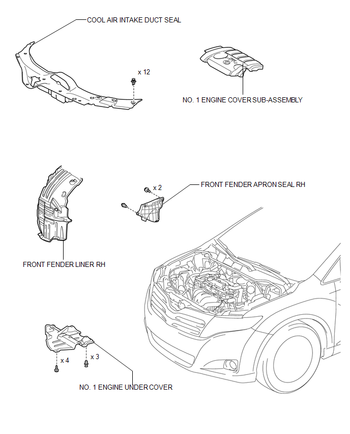
ILLUSTRATION
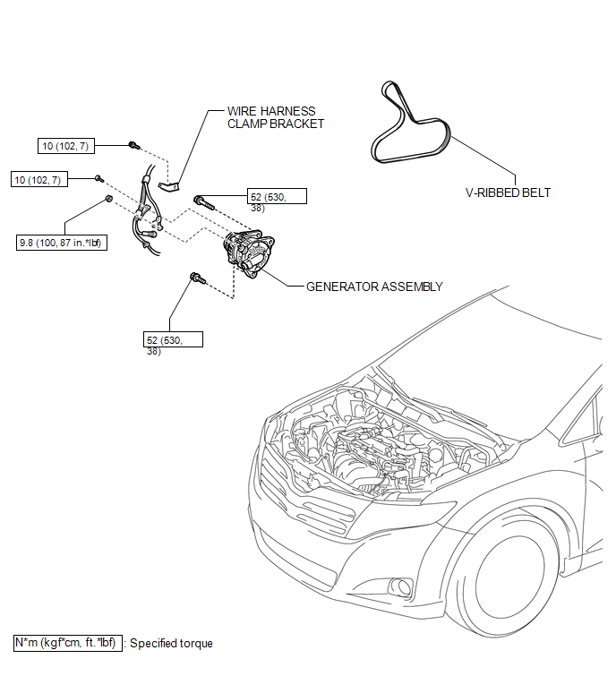
ILLUSTRATION
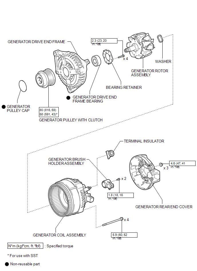
ILLUSTRATION
 Generator
...
 Removal
REMOVAL
PROCEDURE
1. DISCONNECT CABLE FROM NEGATIVE BATTERY TERMINAL
NOTICE:
When disconnecting the cable, some systems need to be initialized after the cable
is reconnected (See page ).
2. RE ...
Other materials about Toyota Venza:
Data List / Active Test
DATA LIST / ACTIVE TEST
1. DATA LIST
HINT:
Using the Techstream to read the Data List allows the values or states of switches,
sensors, actuators and other items to be read without removing any parts. This non-intrusive
inspection can be very useful bec ...
Door Mirror Foot Light Circuit
DESCRIPTION
The main body ECU (driver side junction block assembly) controls the door mirror
foot lights.
WIRING DIAGRAM
1. w/o Seat Position Memory:
2. w/ Seat Position Memory:
PROCEDURE
1.
CHECK VEHICLE CONDITION
...
System Description
SYSTEM DESCRIPTION
1. GENERAL
The rear window defogger wires are attached to the inside of the rear window
and defog the window surface quickly by pressing the rear window defogger switch
on the air conditioning control assembly. The indicator light is i ...

0.1535