Toyota Venza: Disassembly
DISASSEMBLY
PROCEDURE
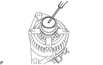
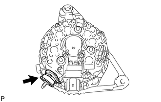
1. REMOVE GENERATOR PULLEY CAP
|
(a) Using a screwdriver, puncture the center of the generator pulley cap and pry it off. NOTICE: Do not reuse the generator pulley cap. |
|
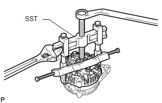
2. REMOVE GENERATOR PULLEY WITH CLUTCH
|
(a) Mount the generator in a vise. Text in Illustration
|
|
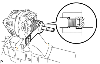
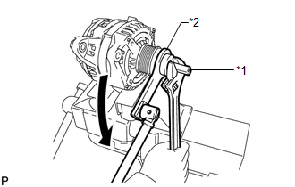
(b) Install SST (A) and (B) to the pulley as shown in the illustration.
SST: 09820-63021
|
(c) Use a wrench to hold SST (A), and turn SST (B) counterclockwise to loosen the generator pulley. Text in Illustration
NOTICE:
|
|
(d) Remove the generator pulley.
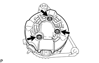
3. REMOVE GENERATOR REAR END COVER
(a) Place the generator on the generator pulley.
|
(b) Remove the 3 nuts and generator rear end cover. |
|
|
(c) Remove the terminal insulator. |
|
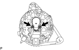
4. REMOVE GENERATOR BRUSH HOLDER ASSEMBLY
|
(a) Remove the 2 screws and generator brush holder. |
|
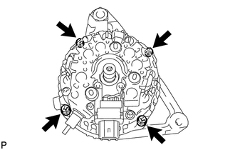
5. REMOVE GENERATOR COIL ASSEMBLY
|
(a) Remove the 4 bolts. |
|
|
(b) Using SST, remove the generator coil. SST: 09950-40011 09951-04020 09952-04010 09953-04020 09954-04010 09955-04071 09957-04010 |
|
6. REMOVE GENERATOR ROTOR ASSEMBLY
|
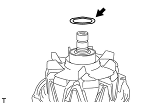
(a) Remove the generator washer. |
|
|
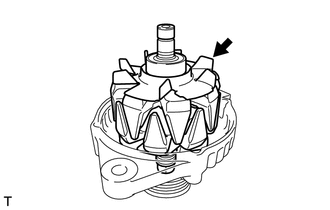
(b) Remove the generator rotor assembly. |
|
 Removal
REMOVAL
PROCEDURE
1. DISCONNECT CABLE FROM NEGATIVE BATTERY TERMINAL
NOTICE:
When disconnecting the cable, some systems need to be initialized after the cable
is reconnected (See page ).
2. RE ...
 Inspection
INSPECTION
PROCEDURE
1. INSPECT GENERATOR PULLEY WITH CLUTCH
(a) Hold the center of the pulley, and confirm that the outer ring turns
counterclockwise and does not turn clockwise.
...
Other materials about Toyota Venza:
Seat Belt Buckle Switch LH Circuit Malfunction (B1656/38)
DESCRIPTION
The seat belt buckle switch LH circuit consists of the center airbag sensor assembly
and front seat inner belt assembly LH.
DTC B1656/38 is stored when a malfunction is detected in the seat belt buckle
switch LH circuit.
DTC No.
...
Precaution
PRECAUTION
NOTICE:
When disconnecting the cable from the negative (-) battery terminal, initialize
the following systems after the cable is reconnected.
System Name
See Procedure
Back Door Closer System
...
Assist Map Number Mismatch (C1582)
DESCRIPTION
When an incorrect ECM or brake actuator assembly (skid control ECU) is installed
after the assist map has been recorded in the power steering ECU, then DTC C1582
is stored because the data does not match the vehicle specifications.
...

0.1537