Toyota Venza: Removal
REMOVAL
CAUTION / NOTICE / HINT
CAUTION:
- Wear protective gloves when removing the exhaust pipe.
- The exhaust pipe is extremely hot immediately after the engine has stopped.
- Confirm that the exhaust pipe has cooled down before removing it.
PROCEDURE
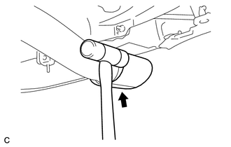
1. REMOVE TAIL EXHAUST PIPE BAFFLE SUB-ASSEMBLY
|
(a) Using a plastic hammer, uniformly tap off the tail exhaust pipe baffle sub-assembly. |
|
2. REMOVE TAIL EXHAUST PIPE ASSEMBLY
|
(a) Remove the 2 bolts and 2 compression springs. |
|
.png)
(b) Disconnect the tail exhaust pipe assembly from the 4 exhaust pipe supports.
(c) Remove the gasket from the center exhaust pipe assembly.
3. REMOVE CENTER EXHAUST PIPE ASSEMBLY
|
(a) Remove the 2 bolts. |
|
.png)
(b) Disconnect the center exhaust pipe assembly from the 2 exhaust pipe supports.
(c) Remove the gasket from the center exhaust pipe assembly.
4. REMOVE FRONT EXHAUST PIPE ASSEMBLY
|
(a) Disconnect the heated oxygen sensor connector. |
|
.png)
|
(b) Remove the 2 bolts, 2 compression springs and front exhaust pipe assembly from the exhaust manifold converter sub-assembly. |
|
.png)
(c) Remove the gasket from the exhaust manifold converter sub-assembly.
5. REMOVE HEATED OXYGEN SENSOR
.gif)
 Installation
INSTALLATION
PROCEDURE
1. INSTALL HEATED OXYGEN SENSOR
2. INSTALL FRONT EXHAUST PIPE ASSEMBLY
(a) Using a vernier caliper, measure the free length of the compression
springs.
...
 Intake Air Control Valve Actuator(for Tcv)
Components
COMPONENTS
ILLUSTRATION
Removal
REMOVAL
PROCEDURE
1. REMOVE INTAKE MANIFOLD
(a) Remove the intake manifold (See page ).
2. REMOVE INTAKE AIR CONTROL VALVE ACTUATOR (for TCV)
...
Other materials about Toyota Venza:
Customize Parameters
CUSTOMIZE PARAMETERS
HINT:
The following items can be customized.
NOTICE:
After confirming whether the items requested by the customer are applicable
or not for customization, perform customizing operations.
Be sure to record the current se ...
Front Passenger Side Door Entry Lock and Unlock Functions do not Operate
DESCRIPTION
When the entry lock and unlock functions do not operate only for the front passenger
door, an error in output request codes from the front passenger door or malfunction
in the front door outside handle assembly is suspected. If the entry funct ...
Back Door Motor Clutch Malfunction (B2225)
DESCRIPTION
When an electrical malfunction (open or short) is detected in the clutch circuit
of the power back door ECU (power back door motor unit) while the power back door
is operating, the power back door ECU (power back door motor unit) stores DTC B2 ...

0.1313