Toyota Venza: Meter Illumination does not Dim at Night
DESCRIPTION
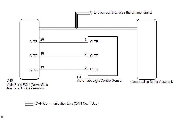
In this circuit, the meter CPU receives auto dimmer signals from the main body ECU (driver side junction block assembly) using the CAN communication system (CAN No. 1 Bus). When the meter CPU receives an auto dimmer signal, it dims the meter illumination (warning and indicator lights). The main body ECU (driver side junction block assembly) determines whether it is daytime, twilight, or nighttime based on the waveform transmitted from the automatic light control sensor. If the main body ECU (driver side junction block assembly) determines that it is nighttime and the light control switch is in the tail, head, or AUTO, the ECU sends an auto dimmer signal. According to the signal, the combination meter assembly dims the meter illumination.
HINT:
When the meter illumination does not dim at night, there may be a malfunction in the automatic light control sensor, main body ECU (driver side junction block assembly), CAN communication system, harness or connector, or combination meter assembly.
WIRING DIAGRAM
CAUTION / NOTICE / HINT
HINT:
- The automatic light control sensor sensitiveness can be customized (See
page
.gif) ).
).
- When the meter illumination setting is 8, the meter illumination does not dim even though the light control switch is tail, head, or AUTO position at night. Therefore, check the meter illumination setting before proceeding to the following steps.
PROCEDURE
|
1. |
CHECK CAN COMMUNICATION SYSTEM |
(a) Check if a CAN communication DTC is output (See page
).
|
Result |
Proceed to |
|---|---|
|
CAN communication DTC is not output. |
A |
|
CAN communication DTC is output. |
B |
| B | .gif) |
GO TO CAN COMMUNICATION SYSTEM |
|
.gif)
|
2. |
CHECK DTC (LIGHT CONTROL SENSOR CIRCUIT) |
(a) Check if DTC B1244 is output (See page
).
|
Result |
Proceed to |
|---|---|
|
B1244 is not output. |
A |
|
B1244 is output. |
B |
| B | |
GO TO LIGHTING SYSTEM |
|
|
3. |
CHECK OPERATION (ACCESSORY METER ASSEMBLY) |
(a) Turn the ignition switch to ON.
(b) Turn the light control switch to the tail, head, or AUTO position.
(c) Cover the light control switch.
(d) Check the accessory meter assembly illumination.
|
Result |
Proceed to |
|---|---|
|
Accessory meter assembly illumination does not operate normally. |
A |
|
Accessory meter assembly illumination operates normally. |
B |
HINT:
The accessory meter assembly illumination dims according to the dimmer signal as the combination meter assembly does. Therefore, when only the meter illumination does not dim at night, replace the combination meter assembly.
| B | |
REPLACE COMBINATION METER ASSEMBLY |
|
|
4. |
CHECK OPERATION (AUTOMATIC LIGHT CONTROL SYSTEM) |
(a) Turn the ignition switch to ON.
(b) Turn the light control switch to the AUTO position.
(c) Cover the automatic light control sensor.
(d) Check that the taillights and low beam headlights.
OK:
The taillights and low beam headlights come on.
(e) Uncover the automatic light control sensor.
(f) Check that the low beam headlights and taillights.
OK:
The low beam headlights and taillights go off.
|
Result |
Proceed to |
|---|---|
|
Automatic light control system operates normally. |
A |
|
Automatic light control system does not operate normally. |
B |
| B | |
CHECK LIGHTING SETTING |
|
|
5. |
REPLACE MAIN BODY ECU (DRIVER SIDE JUNCTION BLOCK ASSEMBLY) |
(a) Replace the main body ECU (driver side junction block assembly) with a new
or a known good one (See page ).
OK:
The operation of the combination meter assembly returns to normal.
HINT:
The meter CPU controls the meter illumination based on an auto dimmer signal from the main body ECU (driver side junction block assembly). If the meter does not dim when the light control switch is in the tail, head, or AUTO position at night, it may be for either of 2 reasons. The first reason is that the main body ECU (driver side junction block assembly) does not send an auto dimmer signal. The second is that the meter CPU does not dim the meter illumination even though the meter CPU receives an auto dimmer signal.
| OK | |
END |
| NG | |
REPLACE COMBINATION METER ASSEMBLY |
 Fuel Receiver Gauge Malfunction
DESCRIPTION
The meter CPU uses the fuel sender gauge assembly to determine the level
of the fuel in the fuel tank. The resistance of the fuel sender gauge will
vary between approximate ...
 Meter Illumination is Always Dark
DESCRIPTION
In this circuit, the meter CPU receives auto dimmer signals from the main body
ECU (driver side junction block assembly) using the CAN communication system (CAN
No. 1 Bus). When the m ...
Other materials about Toyota Venza:
CD cannot be Ejected
PROCEDURE
1.
CHECK OPERATION
(a) Press the disc eject switch of the radio and display receiver assembly for
5 seconds or more and check that the CD is ejected.
OK:
CD is ejected.
NG
REPLACE RADIO AND D ...
Does not Play even after Bluetooth Audio Mode is Selected
CAUTION / NOTICE / HINT
HINT:
Even if the portable player can play audio content, it may not be able to play
via the in-vehicle device. This does not necessarily indicate a malfunction of the
in-vehicle device.
PROCEDURE
1.
CHECK ...
If your vehicle needs to be towed
If towing is necessary, we recommend having your vehicle towed by your Toyota
dealer or a commercial towing service, using a lift-type truck or a flat bed truck.
Use a safety chain system for all towing, and abide by all state/provincial and
local laws.
...

0.1685