Toyota Venza: Intake Air Control Valve Actuator(for Tcv)
Components
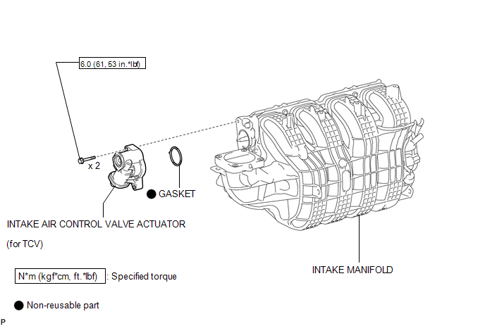
COMPONENTS
ILLUSTRATION
Removal
REMOVAL
PROCEDURE
1. REMOVE INTAKE MANIFOLD
(a) Remove the intake manifold (See page .gif) ).
).
2. REMOVE INTAKE AIR CONTROL VALVE ACTUATOR (for TCV)
(a) Remove the 2 bolts, intake air control valve actuator and gasket from the intake manifold.
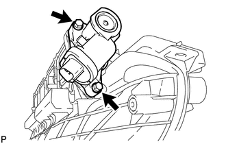
NOTICE:
- Make sure that foreign matter, such as water, oil, sand and iron particles,
does not enter the gear chamber or actuator at the locations marked by the
circles in the illustration.
- Do not loosen or remove the bolt and 2 nuts shown in the illustration.
Inspection
INSPECTION
PROCEDURE
1. INSPECT INTAKE AIR CONTROL VALVE ACTUATOR (for TCV)
(a) Check the intake air control valve actuator operation.
|
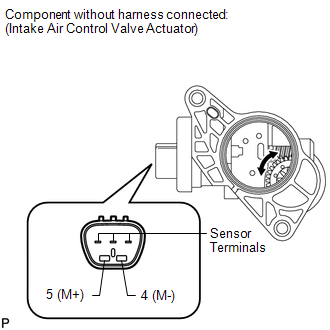
(1) Check that the motor operates when the battery is connected to the terminals of the intake air control valve actuator. NOTICE: If the positive (+) and negative (-) battery leads contact the sensor terminals, the actuator may be damaged. Standard:
If the result is not as specified, replace the intake air control valve actuator. |
|
Installation
INSTALLATION
PROCEDURE
1. INSTALL INTAKE AIR CONTROL VALVE ACTUATOR (for TCV)
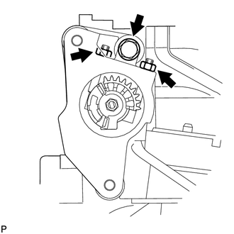
NOTICE:
- Make sure that foreign matter, such as water, oil, sand and iron particles,
does not enter the gear chamber or actuator at the locations marked by the
circles in the illustration.
.png)
- Do not loosen or remove the bolt and 2 nuts shown in the illustration.
.png)
|
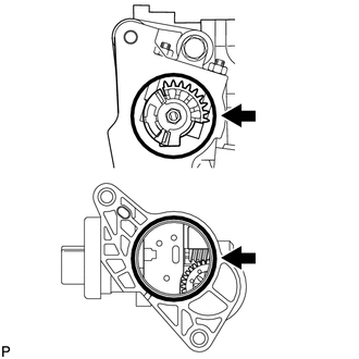
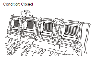
(a) Close the tumble control valves. HINT: If the tumble control valves are not closed, close them by hand. |
|
|
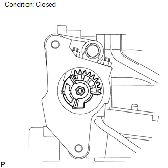
(b) Check that the gear of each tumble control valve is in the position shown in the illustration. HINT: Turn the gear clockwise until it contacts the stopper. |
|
(c) Install a new gasket to the intake air control valve actuator.
|
(d) Install the intake air control valve actuator to the intake manifold with the 2 bolts. Torque: 6.0 N·m {61 kgf·cm, 53 in·lbf} NOTICE:
|
|
.png)
2. INSTALL INTAKE MANIFOLD
(a) Install the intake manifold (See page .gif)
).
 Removal
REMOVAL
CAUTION / NOTICE / HINT
CAUTION:
Wear protective gloves when removing the exhaust pipe.
The exhaust pipe is extremely hot immediately after the engine has stopped.
...
 Intake Manifold
...
Other materials about Toyota Venza:
Installation
INSTALLATION
PROCEDURE
1. INSTALL NO. 1 COOLER THERMISTOR
2. INSTALL COOLER EVAPORATOR SUB-ASSEMBLY
3. INSTALL BLOWER ASSEMBLY WITH COOLER EVAPORATOR SUB-ASSEMBLY
(a) Engage the 5 claws.
(b) Engage the guide and connect the wire harness.
(c) Insta ...
Removal
REMOVAL
PROCEDURE
1. REMOVE ENGINE ASSEMBLY WITH TRANSAXLE
(a) Remove the engine and transaxle (See page
).
2. REMOVE EXHAUST MANIFOLD CONVERTER SUB-ASSEMBLY
(a) Remove the exhaust manifold converter (See page
).
3. REMOVE THROTTLE BODY ASSEMBLY
...
Removal
REMOVAL
PROCEDURE
1. REMOVE AIR CONDITIONING UNIT ASSEMBLY
(See page )
2. REMOVE NO. 1 FINISH PANEL MOUNTING BRACKET
3. REMOVE NO. 2 FINISH PANEL MOUNTING BRACKET
4. REMOVE NO. 3 AIR DUCT SUB-ASSEMBLY
5. REMOVE NO. 2 AIR DUCT SUB-ASSEMBLY
...

0.1653