Toyota Venza: Removal
REMOVAL
CAUTION / NOTICE / HINT
CAUTION:
- Wear protective gloves when removing the exhaust pipe.
- The exhaust pipe is extremely hot immediately after the engine has stopped.
- Confirm that the exhaust pipe has cooled down before removing it.
PROCEDURE
1. REMOVE NO. 1 ENGINE UNDER COVER
2. REMOVE NO. 2 ENGINE UNDER COVER
3. REMOVE FRONT EXHAUST PIPE ASSEMBLY
|
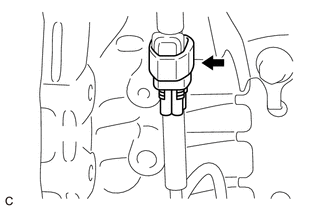
(a) Disconnect the heated oxygen sensor connector. |
|
|
(b) Remove the 4 bolts, 2 compression springs and front exhaust pipe assembly from the exhaust manifold converter sub-assembly and center exhaust pipe assembly. |
|
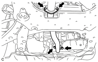
(c) Remove the 2 gaskets from the exhaust manifold converter sub-assembly and center exhaust pipe assembly.
4. REMOVE AIR FUEL RATIO SENSOR
.gif)
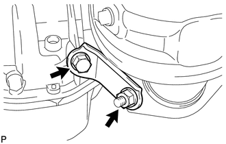
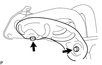
5. REMOVE MANIFOLD STAY
|
(a) Remove the bolt, nut and manifold stay from the exhaust manifold converter sub-assembly and stiffening crankcase assembly. |
|
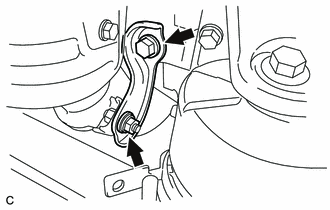
6. REMOVE NO. 2 MANIFOLD STAY
|
(a) Remove the bolt, nut and No. 2 manifold stay from the exhaust manifold converter sub-assembly and stiffening crankcase assembly. |
|
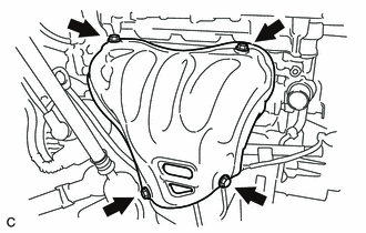
7. REMOVE NO. 1 EXHAUST MANIFOLD HEAT INSULATOR
|
(a) Remove the 4 bolts and No. 1 exhaust manifold heat insulator from the exhaust manifold converter sub-assembly. |
|
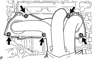
8. REMOVE EXHAUST MANIFOLD CONVERTER SUB-ASSEMBLY
|
(a) Remove the 5 nuts and exhaust manifold converter sub-assembly from the cylinder head sub-assembly. |
|
|
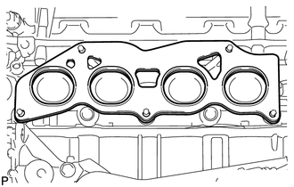
(b) Remove the gasket from the cylinder head sub-assembly. |
|
9. REMOVE NO. 2 EXHAUST MANIFOLD HEAT INSULATOR
|
(a) Remove the 2 bolts and No. 2 exhaust manifold heat insulator from the exhaust manifold converter sub-assembly. |
|
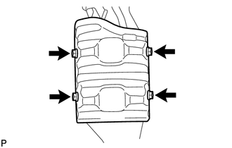
10. REMOVE NO. 1 MANIFOLD CONVERTER INSULATOR
|
(a) Remove the 4 bolts and No. 1 manifold converter insulator from the exhaust manifold converter sub-assembly. |
|
 Components
COMPONENTS
ILLUSTRATION
ILLUSTRATION
...
 Installation
INSTALLATION
PROCEDURE
1. INSTALL NO. 1 MANIFOLD CONVERTER INSULATOR
(a) Install the No. 1 manifold converter insulator to the exhaust manifold
converter sub-assembly with the 4 bolt ...
Other materials about Toyota Venza:
Garage Door Opener Switch
Components
COMPONENTS
ILLUSTRATION
Removal
REMOVAL
PROCEDURE
1. REMOVE ROOF CONSOLE BOX ASSEMBLY (GARAGE DOOR OPENER SWITCH)
(a) Using a moulding remover, disengage the 2 claws and 2 clips.
Text in Illustration
*1 ...
Security Indicator Light Circuit
DESCRIPTION
Even when the theft deterrent system is in the disarmed state, the security indicator
blinks due to a signal output from the immobiliser system. The security indicator
blinks continuously due to a continuous signal received from the immobilise ...
Speed Signal Malfunction (B15C2)
DESCRIPTION
The navigation receiver assembly receives a vehicle speed signal from the combination
meter assembly and information from the navigation antenna assembly, and then adjusts
the vehicle position.
The navigation receiver assembly stores this DTC ...

0.1266