Toyota Venza: Removal
REMOVAL
PROCEDURE
1. REMOVE REAR WHEELS
2. REMOVE CENTER EXHAUST PIPE ASSEMBLY
(a) Remove the center exhaust pipe assembly.
HINT:
Refer to the instructions for Removal of the exhaust pipe (See page
.gif) for 2GR-FE,
for 2GR-FE,
for 1AR-FE).
3. REMOVE PROPELLER WITH CENTER BEARING SHAFT ASSEMBLY
4. SEPARATE REAR SPEED SENSOR LH
|
(a) Remove the bolt and separate the rear speed sensor LH from the rear axle carrier sub-assembly. NOTICE: Keep the sensor tip and rear speed sensor installation hole free from foreign matter. |
|
.png)
|
(b) Remove the bolt and separate the rear speed sensor LH from the rear shock absorber with coil spring. |
|
.png)
5. SEPARATE REAR SPEED SENSOR RH
HINT:
Perform the same procedure as the LH side.
6. REMOVE REAR AXLE SHAFT NUT LH
7. REMOVE REAR AXLE SHAFT NUT RH
HINT:
Perform the same procedure as the LH side.
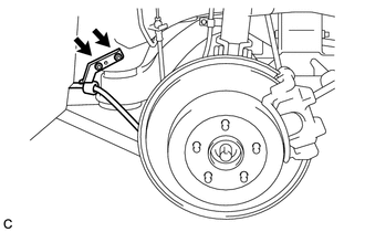
8. SEPARATE NO. 3 PARKING BRAKE CABLE ASSEMBLY
|
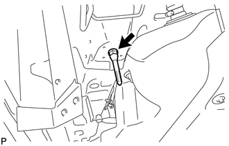
(a) Remove the bolt and separate the No. 3 parking brake cable assembly. |
|
.png)
|
(b) Remove the 2 nuts and separate the No. 3 parking brake cable assembly. |
|
9. SEPARATE NO. 2 PARKING BRAKE CABLE ASSEMBLY
HINT:
Perform the same procedure as the No. 3 parking brake cable assembly.
10. REMOVE NO. 1 FLOOR UNDER COVER
11. REMOVE REAR STRUT ROD ASSEMBLY LH
12. REMOVE REAR STRUT ROD ASSEMBLY RH
13. REMOVE REAR HEIGHT CONTROL SENSOR SUB-ASSEMBLY (w/ HID Headlight System)
14. REMOVE REAR NO. 2 SUSPENSION ARM ASSEMBLY LH
15. REMOVE REAR NO. 2 SUSPENSION ARM ASSEMBLY RH
16. SEPARATE REAR NO. 1 SUSPENSION ARM ASSEMBLY LH
17. SEPARATE REAR NO. 1 SUSPENSION ARM ASSEMBLY RH
18. DRAIN DIFFERENTIAL OIL
19. REMOVE REAR DRIVE SHAFT ASSEMBLY LH
20. REMOVE REAR DRIVE SHAFT SNAP RING LH
21. REMOVE REAR DRIVE SHAFT ASSEMBLY RH
HINT:
Perform the same procedure as the LH side.
22. REMOVE REAR DRIVE SHAFT SNAP RING RH
HINT:
Perform the same procedure as the LH side.
23. SEPARATE NO. 3 FLOOR WIRE (w/ HID Headlight System)
|
(a) Disengage the clamp to separate the No. 3 floor wire from the rear suspension member. |
|
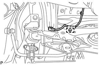
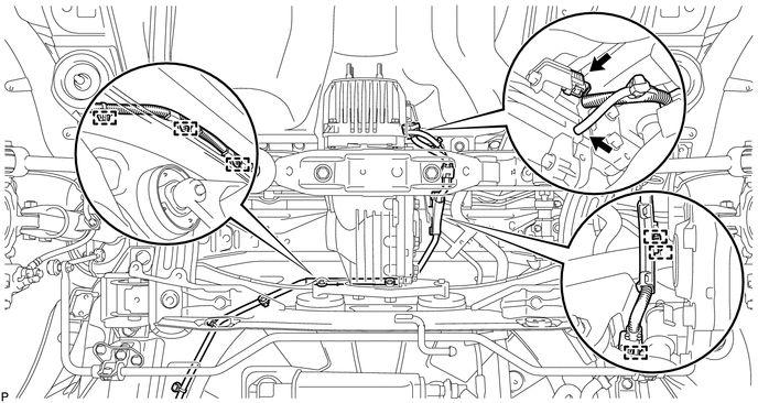
24. SEPARATE FRAME WIRE
(a) Disconnect the connector, separate the hose, and then disengage the 6 clamps to separate the frame wire.
25. REMOVE REAR SUSPENSION MEMBER
|
(a) Support the rear suspension member with a jack using 3 wooden blocks as shown in the illustration. Text in Illustration
HINT: Use properly sized wooden blocks to keep the jack and suspension member level. |
|
.png)
(b) Remove the 4 nuts, 2 bolts and 2 rear lower suspension member stopper retainers.
.png)
(c) Lower the rear suspension member.
NOTICE:
When lowering the rear suspension member, be careful not to damage the vehicle body or other components installed on the vehicle.
(d) Remove the 2 rear upper suspension member stoppers.
26. REMOVE REAR NO. 1 SUSPENSION ARM ASSEMBLY LH
|
(a) Remove the bolt, nut and rear No. 1 suspension arm assembly LH from the rear suspension member. NOTICE: Since a stopper nut is used, loosen the bolt. |
|
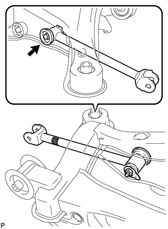
27. REMOVE REAR NO. 1 SUSPENSION ARM ASSEMBLY RH
HINT:
Perform the same procedure as the LH side.
28. REMOVE REAR DIFFERENTIAL CARRIER ASSEMBLY WITH DIFFERENTIAL SUPPORT
29. REMOVE REAR NO. 1 DIFFERENTIAL MOUNT CUSHION
30. REMOVE REAR NO. 2 DIFFERENTIAL MOUNT CUSHION
31. REMOVE REAR SUSPENSION MEMBER BODY MOUNTING FRONT CUSHION (for LH Side)
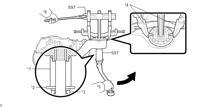
(a) Using SST, remove the rear suspension member body mounting front cushion.
 Text in Illustration
|
*1 |
Spacer No. 1 |
*2 |
Washer |
|
*3 |
Bearing |
*4 |
Claw |
|
*5 |
Turn |
*6 |
Hold |
SST: 09830-10010
09830-01010
09830-01040
09830-01050
SST: 09950-40011
09951-04020
09952-04010
09954-04010
09955-04011
09958-04011
NOTICE:
- Set the tips of the claws in the cutouts of the body mounting cushion.
- Securely install the spacer No. 1 to the inner cylinder of the body mounting cushion as shown in the illustration.
- Apply a small amount of grease to the threads of SST (center bolt) before use.
- Tighten SST slowly and evenly.
- Be careful as the body mounting cushion may fly out.
- The body mounting cushion cannot be reused.
32. REMOVE REAR SUSPENSION MEMBER BODY MOUNTING FRONT CUSHION (for RH Side)
HINT:
Perform the same procedure as the LH side.
33. REMOVE REAR SUSPENSION MEMBER BODY MOUNTING REAR CUSHION (for LH Side)
|
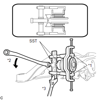
(a) Using SST, temporarily remove the rear suspension member body mounting rear cushion. Text in Illustration
SST: 09710-30050 SST: 09950-40011 09951-04020 09952-04010 09953-04010 09954-04010 09955-04031 09958-04011 NOTICE:
|
|
|
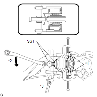
(b) When the mounting cushion protrudes approximately 6 mm, reassemble SST as shown in the illustration and remove the mounting cushion. Text in Illustration
SST: 09710-30050 SST: 09950-40011 09951-04020 09952-04010 09953-04010 09953-04020 09954-04010 09955-04031 09958-04011 NOTICE:
HINT: Use the shorter center bolt first, and then change it to the longer center bolt. |
|
34. REMOVE REAR SUSPENSION MEMBER BODY MOUNTING REAR CUSHION (for RH Side)
HINT:
Perform the same procedure as the LH side.
35. REMOVE HOLE PLUG
(a) Remove the 6 hole plugs.
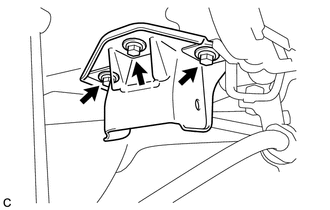
36. REMOVE REAR NO. 2 BODY MOUNTING BRACKET SUB-ASSEMBLY LH
|
(a) Remove the 3 bolts and rear No. 2 body mounting bracket sub-assembly LH. |
|
37. REMOVE REAR NO. 2 BODY MOUNTING BRACKET SUB-ASSEMBLY RH
HINT:
Perform the same procedure as the LH side.
38. REMOVE STUD BOLT (for LH Side)
|
(a) Remove the stud bolt. |
|
39. REMOVE STUD BOLT (for RH Side)
HINT:
Perform the same procedure as the LH side.
 Components
COMPONENTS
ILLUSTRATION
ILLUSTRATION
ILLUSTRATION
ILLUSTRATION
ILLUSTRATION
ILLUSTRATION
...
 Installation
INSTALLATION
PROCEDURE
1. INSTALL STUD BOLT (for LH Side)
(a) Using SST and a socket wrench (21 mm), install the stud bolt.
Text in Illustration
*1
...
Other materials about Toyota Venza:
Illumination Circuit
DESCRIPTION
Power is supplied to the navigation receiver assembly and steering pad switch
assembly illumination when the light control switch is in the tail or head position.
WIRING DIAGRAM
CAUTION / NOTICE / HINT
NOTICE:
The vehicle is equipp ...
On-vehicle Inspection
ON-VEHICLE INSPECTION
PROCEDURE
1. INSPECT REAR COMBINATION LIGHT ASSEMBLY
(a) Disconnect the connector from the rear combination light assembly.
(b) Measure the voltage according to the value(s) in ...
Rear Window Defogger System does not Operate
DESCRIPTION
When the rear window defogger switch on the air conditioning control assembly
is pressed, the operation signal is transmitted to the air conditioning amplifier
assembly through the LIN communication line. When the air conditioning amplifier
...

0.1743