Toyota Venza: Rear Light Assembly
Components
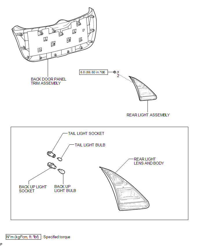
COMPONENTS
ILLUSTRATION
On-vehicle Inspection
ON-VEHICLE INSPECTION
PROCEDURE
1. INSPECT REAR LIGHT ASSEMBLY
|
(a) Disconnect the connector from the rear light assembly. |
|
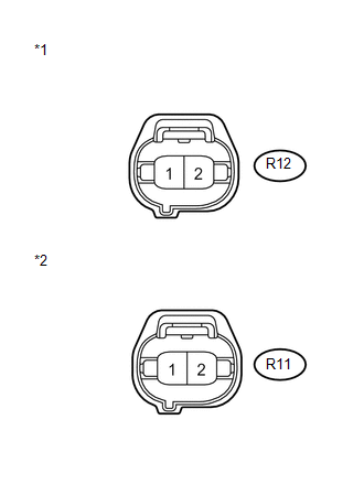
(b) Measure the voltage according to the value(s) in the table below.
Standard Voltage:
LH Side|
Tester Connection |
Condition |
Specified Condition |
|---|---|---|
|
R12-1 - R12-2 |
Light control switch in tail position |
11 to 14 V |
|
Light control switch off |
Below 1 V |
|
Tester Connection |
Condition |
Specified Condition |
|---|---|---|
|
R11-1 - R11-2 |
Light control switch in tail position |
11 to 14 V |
|
Light control switch off |
Below 1 V |
|
*1 |
Front view of wire harness connector (to Rear Light Assembly LH) |
|
*2 |
Front view of wire harness connector (to Rear Light Assembly RH) |
If the result is not as specified, repair or replace the wire harness or connector.
Disassembly
DISASSEMBLY
PROCEDURE
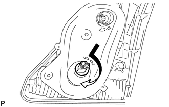
1. REMOVE TAIL LIGHT BULB
|
(a) Turn the tail light bulb and the tail light socket in the direction indicated by the arrow shown in the illustration and remove them as a unit. |
|
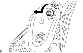
(b) Remove the tail light bulb from the tail light socket.
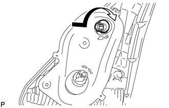
2. REMOVE BACK UP LIGHT BULB
|
(a) Turn the back up light bulb and the back up light socket in the direction indicated by the arrow shown in the illustration and remove them as a unit. |
|
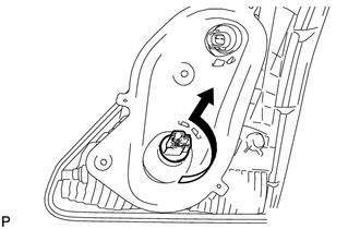
(b) Remove the back up light bulb from the back up light socket.
Removal
REMOVAL
PROCEDURE
1. REMOVE BACK DOOR PANEL TRIM ASSEMBLY
.gif)
2. REMOVE REAR LIGHT ASSEMBLY
|
(a) Disconnect the 2 connectors. |
|
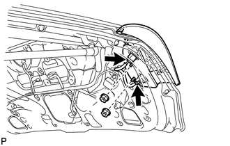
(b) Remove the 2 nuts.
|
(c) Disengage the 2 pins and remove the rear light assembly. |
|
Installation
INSTALLATION
PROCEDURE
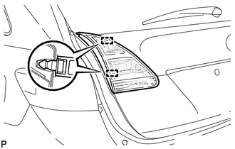
1. INSTALL REAR LIGHT ASSEMBLY
|
(a) Engage the 2 pins to install the rear light assembly. |
|
.png)
|
(b) Install the 2 nuts. Torque: 6.8 N·m {69 kgf·cm, 60 in·lbf} |
|
.png)
(c) Connect the 2 connectors.
2. INSTALL BACK DOOR PANEL TRIM ASSEMBLY
.gif)
Reassembly
REASSEMBLY
PROCEDURE
1. INSTALL BACK UP LIGHT BULB
(a) Install the back up light bulb to the back up light socket.
|
(b) Turn the back up light bulb to the back up light socket in the direction indicated by the arrow shown in the illustration to install them as a unit. |
|
2. INSTALL TAIL LIGHT BULB
(a) Install the tail light bulb to the tail light socket.
|
(b) Turn the tail light bulb to the tail light socket in the direction indicated by the arrow shown in the illustration to install them as a unit. |
|
 Installation
INSTALLATION
PROCEDURE
1. INSTALL REAR COMBINATION LIGHT ASSEMBLY
(a) Engage the guide and 2 pins, and install the rear combination light
assembly as shown in the illustration.
Te ...
 Relay
Relay
On-vehicle Inspection
ON-VEHICLE INSPECTION
PROCEDURE
1. INSPECT TAILLIGHT RELAY (TAIL)
(a) Remove the taillight relay from the main body ECU (driver side junction
block assembly) ...
Other materials about Toyota Venza:
Disassembly
DISASSEMBLY
PROCEDURE
1. REMOVE TRANSMISSION WIRE
2. REMOVE ATF TEMPERATURE SENSOR ASSEMBLY
(a) Remove the 4 bolts, ATF temperature sensor assembly and clamp from
the valve body assembly.
Text in Illustration
*1
...
All Door Entry Lock/Unlock Functions and Wireless Functions do not Operate
DESCRIPTION
When the entry door lock and unlock functions and wireless door lock and unlock
functions do not operate, radio wave interference, or a malfunction in the key or
signal circuit between the door control receiver assembly and certification ECU
...
Data Signal Circuit between Navigation Receiver Assembly and Extension Module
DESCRIPTION
The stereo component tuner assembly sends the image data signal to the navigation
receiver assembly via this circuit.
WIRING DIAGRAM
PROCEDURE
1.
CHECK NAVIGATION WIRE
(a) Remove the navigation wire (See pag ...

0.1218