Toyota Venza: Components
COMPONENTS
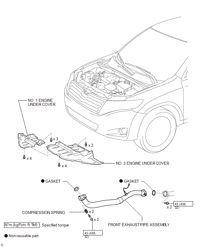
ILLUSTRATION
ILLUSTRATION
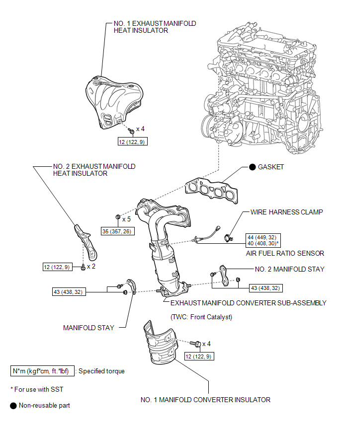
 Exhaust Manifold
...
 Removal
REMOVAL
CAUTION / NOTICE / HINT
CAUTION:
Wear protective gloves when removing the exhaust pipe.
The exhaust pipe is extremely hot immediately after the engine has stopped.
...
Other materials about Toyota Venza:
Stereo Component Amplifier Malfunction (B15A3)
DESCRIPTION
This DTC is stored when a malfunction occurs in the stereo component amplifier
assembly.
DTC No.
DTC Detection Condition
Trouble Area
B15A3
When any of the following conditions is met ...
Replacement
REPLACEMENT
PROCEDURE
1. REPLACE RING PIN
NOTICE:
It is not necessary to remove the ring pin unless it is being replaced.
(a) Remove the 12 ring pins.
(b) Using a plastic-faced hammer, install 12 new ring pins.
Standard Protrusion Height:
...
Short in Curtain Shield Squib LH Circuit (B1835/58-B1838/58)
DESCRIPTION
The curtain shield squib LH circuit consists of the center airbag sensor assembly
and curtain shield airbag assembly LH.
The center airbag sensor assembly uses this circuit to deploy the airbag when
deployment conditions are met.
These DTCs ...

0.1567