Toyota Venza: Reassembly
REASSEMBLY
PROCEDURE
1. INSTALL MULTIPLEX NETWORK DOOR ECU
|
(a) Connect the connector and install the multiplex network door ECU. |
|
.png)
|
(b) Install the flat cable connector as shown in the illustration. |
|
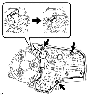
(c) Install the 3 screws.
|
(d) Engage the 4 claws to install the cover. |
|
.png)
 Disassembly
DISASSEMBLY
CAUTION / NOTICE / HINT
NOTICE:
When disassembling the multiplex network door ECU, eliminate static electricity
by touching the vehicle body to prevent the components from being damag ...
 Installation
INSTALLATION
PROCEDURE
1. INSTALL POWER BACK DOOR UNIT ASSEMBLY
(a) Install the power back door unit with the 4 bolts.
Torque:
13 N·m {133 kgf·cm, 10 ft·lbf}
...
Other materials about Toyota Venza:
Back-up Power Source Circuit
DESCRIPTION
The back-up power source circuit for the A/C amplifier is shown below. Power
is supplied even when the ignition switch is turned off. The power is used for diagnostic
trouble code memory, etc.
WIRING DIAGRAM
CAUTION / NOTICE / HINT
NOTICE ...
Precaution
PRECAUTION
1. PRECAUTION FOR DISCONNECTING BATTERY CABLE
NOTICE:
When disconnecting the cable from the negative (-) battery terminal, initialize
the following systems after the cable is reconnected.
System
See Procedure
...
Screen Flicker or Color Distortion
PROCEDURE
1.
CHECK DISPLAY SETTING
(a) Reset display settings (contrast, brightness) and check that the screen appears
normal.
OK:
The display returns to normal.
OK
END
NG
...

0.1327