Toyota Venza: Replacement
REPLACEMENT
CAUTION / NOTICE / HINT
HINT:
- Use the same procedure for the RH side and LH side.
- The procedure listed below is for the LH side.
PROCEDURE
1. DRAIN DIFFERENTIAL OIL
.gif)
2. REMOVE REAR WHEEL
3. REMOVE CENTER EXHAUST PIPE ASSEMBLY (for RH Side)
(a) Remove the center exhaust pipe assembly.
HINT:
Refer to the instructions for Removal of the exhaust pipe (See page
for 2GR-FE,
for 1AR-FE).
4. SEPARATE REAR SPEED SENSOR
5. REMOVE REAR AXLE SHAFT NUT
6. SEPARATE NO. 3 PARKING BRAKE CABLE ASSEMBLY
7. REMOVE REAR STRUT ROD ASSEMBLY
8. SEPARATE REAR HEIGHT CONTROL SENSOR SUB-ASSEMBLY (w/ HID Headlight System)
9. REMOVE REAR NO. 2 SUSPENSION ARM ASSEMBLY
10. SEPARATE REAR NO. 1 SUSPENSION ARM ASSEMBLY
11. REMOVE REAR DRIVE SHAFT ASSEMBLY
|
(a) Put matchmarks on the rear drive shaft assembly and rear axle hub. Text in Illustration
|
|
|
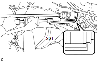
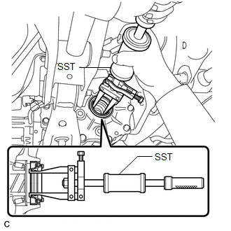
(b) Using SST, disengage the rear drive shaft assembly from the rear differential carrier assembly. SST: 09520-01010 SST: 09520-24010 09520-32040 NOTICE: Remove the rear drive shaft assembly while keeping it level. |
|
|
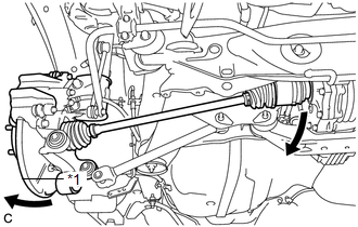
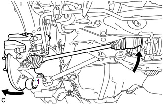
(c) Separate the rear drive shaft assembly from the rear differential carrier assembly while pushing the rear axle assembly towards the outside of the vehicle. Text in Illustration
NOTICE: Do not disjoint inboard of the drive shaft. |
|
|
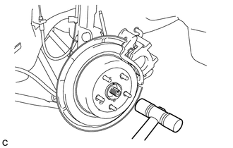
(d) Using a plastic hammer, remove the rear drive shaft assembly from the rear axle assembly. NOTICE: Do not drop the rear drive shaft assembly. |
|
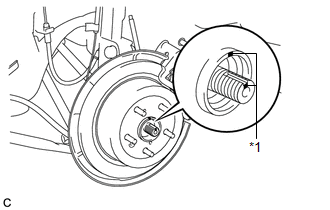
12. REMOVE REAR DRIVE SHAFT SNAP RING
13. REMOVE REAR DIFFERENTIAL SIDE GEAR SHAFT OIL SEAL
|
(a) Using SST, remove the rear differential side gear shaft oil seal from the differential carrier assembly. SST: 09308-00010 |
|
14. INSTALL REAR DIFFERENTIAL SIDE GEAR SHAFT OIL SEAL
|
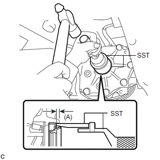
(a) Using SST and a hammer, install a new rear differential side gear shaft oil seal into the differential carrier assembly. SST: 09223-46011 SST: 09631-32020 Standard Distance (A): 8.2 to 8.8 mm (0.323 to 0.346 in.) NOTICE:
|
|
15. INSTALL REAR DRIVE SHAFT SNAP RING
16. INSTALL REAR DRIVE SHAFT ASSEMBLY
|
(a) Align the matchmarks and insert the rear drive shaft assembly to the rear axle assembly. Text in Illustration
|
|
|
(b) Insert the rear drive shaft assembly to the rear differential carrier assembly while pushing the rear axle assembly towards the outside of the vehicle. Text in Illustration
NOTICE: Do not disjoint inboard of the drive shaft. |
|
|
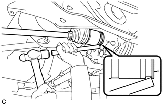
(c) Using a brass bar and a hammer, engage the rear drive shaft assembly to the rear differential carrier assembly. NOTICE:
|
|
17. CONNECT REAR NO. 1 SUSPENSION ARM ASSEMBLY
18. INSTALL REAR NO. 2 SUSPENSION ARM ASSEMBLY
19. INSTALL REAR HEIGHT CONTROL SENSOR SUB-ASSEMBLY (w/ HID Headlight System)
20. INSTALL REAR STRUT ROD ASSEMBLY
21. CONNECT NO. 3 PARKING BRAKE CABLE ASSEMBLY
22. INSTALL REAR AXLE SHAFT NUT
23. CONNECT REAR SPEED SENSOR
24. INSTALL CENTER EXHAUST PIPE ASSEMBLY (for RH Side)
(a) Install the center exhaust pipe assembly.
HINT:
Refer to the instructions for Installation of the exhaust pipe (See page
for 2GR-FE,
for 1AR-FE).
25. ADD DIFFERENTIAL OIL
|
(a) Remove the rear differential carrier cover plug. |
|
.png)
(b) Add differential oil (See page ).
26. INSPECT DIFFERENTIAL OIL
27. INSTALL REAR DIFFERENTIAL CARRIER COVER PLUG
28. INSPECT FOR DIFFERENTIAL OIL LEAK
29. INSTALL REAR WHEEL
Torque:
103 N·m {1050 kgf·cm, 76 ft·lbf}
30. STABILIZE SUSPENSION
31. FULLY TIGHTEN REAR NO. 2 SUSPENSION ARM ASSEMBLY
32. INSPECT AND ADJUST REAR WHEEL ALIGNMENT
(a) Inspect and adjust the rear wheel alignment (See page
).
33. CHECK FOR SPEED SENSOR SIGNAL
(a) Check for the speed sensor signal (See page
).
34. HEIGHT CONTROL SENSOR SIGNAL INITIALIZATION (w/ HID Headlight System)
(a) Initialize the height control sensor signal (See page
).
35. INSPECT AND ADJUST HEADLIGHT AIMING (w/ HID Headlight System)
(a) Inspect and adjust the headlight aiming (See page
).
 Components
COMPONENTS
ILLUSTRATION
ILLUSTRATION
ILLUSTRATION
...
 Steering Knuckle
Components
COMPONENTS
ILLUSTRATION
Removal
REMOVAL
CAUTION / NOTICE / HINT
HINT:
Use the same procedure for the RH side and LH side.
The procedure listed below is for the LH s ...
Other materials about Toyota Venza:
Installation
INSTALLATION
PROCEDURE
1. INSTALL SEPARATE TYPE FRONT SEAT CUSHION COVER
(a) Using a tacker, install the separate type front seat cushion heater
to the end of the separate type front seat cushion cover with 25 new tack
pins.
NOTICE:
...
Diagnostic Trouble Code Chart
DIAGNOSTIC TROUBLE CODE CHART
HINT:
If a trouble code is displayed during the DTC check, inspect the trouble areas
listed for that code. For details of the code, refer to the following "See page".
Back Door Closer System
DTC Code
...
No Signal from Transmitter ID1 (C2121/21-C2124/24,C2181/81-C2184/84)
DESCRIPTION
The tire pressure warning valve and transmitter installed in each tire and wheel
assembly measures the tire pressures. The measured values are transmitted as radio
waves to the tire pressure warning antenna and receiver on the body and then se ...

0.1335