Toyota Venza: Inspection
INSPECTION
PROCEDURE
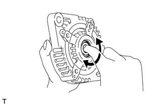
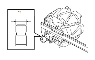
1. INSPECT GENERATOR CLUTCH PULLEY
|
(a) Hold the generator rotor using SST, and turn the clutch pulley clockwise to check that the outer ring locks. SST: 09820-63021 Text in Illustration
If the result is not as specified, replace the clutch pulley. |
|
.png)
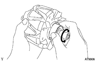
2. INSPECT GENERATOR DRIVE END FRAME BEARING
|
(a) Check that the bearing is not rough or worn. OK: The bearing rotates smoothly. If the bearing does not rotate smoothly, replace the bearing. |
|
3. INSPECT GENERATOR BRUSH HOLDER ASSEMBLY
|
(a) Using a vernier caliper, measure the length of the exposed brushes. Text in Illustration
Standard exposed brush length: 9.5 to 11.5 mm (0.375 to 0.452 in.) Minimum exposed brush length: 4.5 mm (0.178 in.) If the exposed brush length is less than the minimum, replace the brush holder assembly. |
|
.png)
4. INSPECT GENERATOR ROTOR ASSEMBLY
|
(a) Check that the generator rotor bearing is not rough or worn. If necessary, replace the generator rotor assembly. |
|
|
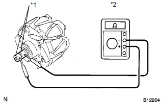
(b) Check the generator rotor for an open circuit. Text in Illustration
(1) Using an ohmmeter, measure the resistance between the slip rings. Standard Resistance:
If the result is not as specified, replace the generator rotor assembly. |
|
||||||||||||||
|
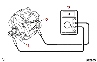
(c) Check the rotor for a short to ground. Text in Illustration
(1) Using an ohmmeter, measure the resistance between the slip ring and rotor. Standard Resistance:
If the result is not as specified, replace the generator rotor assembly. |
|
|
(d) Using a vernier caliper, measure the slip ring diameter. Text in Illustration
Standard diameter: 14.2 to 14.4 mm (0.560 to 0.566 in.) Minimum diameter: 14.0 mm (0.552 in.) If the diameter is less than the minimum, replace the generator rotor assembly. |
|
 Disassembly
DISASSEMBLY
PROCEDURE
1. REMOVE GENERATOR REAR END COVER
(a) Remove the 3 nuts and generator rear end cover.
2. REMOVE TERMINAL INSULATOR
...
 Replacement
REPLACEMENT
PROCEDURE
1. REPLACE GENERATOR DRIVE END FRAME BEARING
(a) Remove the 4 screws and bearing retainer from the drive end frame.
...
Other materials about Toyota Venza:
Taillight Relay Circuit
DESCRIPTION
The main body ECU (driver side junction block assembly) controls the operation
of the TAIL relay.
WIRING DIAGRAM
CAUTION / NOTICE / HINT
NOTICE:
Inspect the fuses for circuits related to this system before performing the following
inspec ...
Indicator Circuit
DESCRIPTION
The headlight beam level control system indicator light in the combination meter
assembly comes on for approximately 3 seconds when the ignition switch is turned
to ON. The indicator light also comes on when the headlight leveling ECU assembly ...
Installation
INSTALLATION
CAUTION / NOTICE / HINT
NOTICE:
When disconnecting the steering intermediate shaft assembly and pinion shaft
of steering gear assembly, be sure to place matchmarks before servicing.
PROCEDURE
1. INSTALL TIE ROD ASSEMBLY LH
(a) I ...

0.2027