Toyota Venza: Installation
INSTALLATION
PROCEDURE
1. INSTALL POWER BACK DOOR UNIT ASSEMBLY
|
(a) Install the power back door unit with the 4 bolts. Torque: 13 N·m {133 kgf·cm, 10 ft·lbf} |
|
.png)
(b) Connect the connector.
2. INSTALL POWER BACK DOOR ROD
(a) When reusing the power back door rod:
|
(1) Install the 2 stop rings to the power back door rod. |
|
|
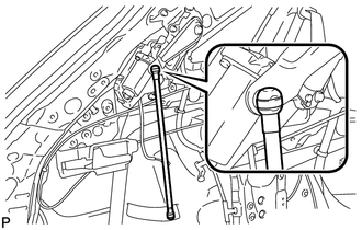
(b) Engage the power back door rod. |
|
|
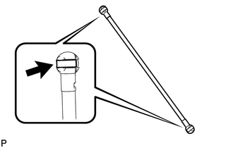
(c) Install the power back door rod. |
|
.png)
(d) Check that the power back door rod is engaged in the ball joint and that the power back door rod cannot be pulled out.
3. INSTALL ROOF SIDE INNER GARNISH ASSEMBLY LH
.gif)
4. INSTALL DECK TRIM SIDE PANEL ASSEMBLY LH
5. CONNECT REAR SEAT OUTER BELT ASSEMBLY LH
6. INSTALL LUGGAGE HOLD BELT STRIKER ASSEMBLY LH
7. INSTALL RECLINING REMOTE CONTROL BEZEL LH
8. INSTALL REAR SEAT ASSEMBLY LH
9. CONNECT REAR SEAT NO. 2 RECLINING CONTROL CABLE SUB-ASSEMBLY
10. INSTALL REAR SEAT OUTER TRACK BRACKET COVER LH
11. INSTALL REAR SEAT INNER TRACK BRACKET COVER LH
12. INSTALL REAR SEAT HEADREST ASSEMBLY LH
13. INSTALL REAR FLOOR FINISH PLATE
14. INSTALL REAR SEAT SUB FLOOR PANEL ASSEMBLY
15. INSTALL NO. 1 DECK BOARD
16. INSTALL DECK SIDE TRIM BOX LH
17. INSTALL NO. 3 DECK BOARD SUB-ASSEMBLY
18. INSTALL DECK SIDE TRIM BOX RH
19. INSTALL NO. 2 DECK BOARD SUB-ASSEMBLY
20. INSTALL DECK BOARD ASSEMBLY
21. INSTALL TONNEAU COVER ASSEMBLY (w/ Tonneau Cover)
22. CONNECT REAR DOOR OPENING TRIM WEATHERSTRIP LH
23. INSTALL REAR DOOR SCUFF PLATE LH
24. INITIALIZE EASY CLOSER SYSTEM
(See page )
25. INITIALIZE POWER BACK DOOR SYSTEM
(See page )
 Reassembly
REASSEMBLY
PROCEDURE
1. INSTALL MULTIPLEX NETWORK DOOR ECU
(a) Connect the connector and install the multiplex network door ECU.
...
 Power Back Door Main Switch
Components
COMPONENTS
ILLUSTRATION
Inspection
INSPECTION
PROCEDURE
1. INSPECT POWER BACK DOOR MAIN SWITCH
(a) Check that the switch function.
(1) Measure the resistance according to th ...
Other materials about Toyota Venza:
Brake Pedal Load Sensing Switch (C1267/67)
DESCRIPTION
The brake pedal load sensing switch is turned on when the brake pedal is depressed
with force exceeding a predetermined level.
The skid control ECU detects if the brake pedal is depressed or not via this
circuit.
DTC Code
...
Installation
INSTALLATION
CAUTION / NOTICE / HINT
HINT:
Use the same procedure for the LH side and RH side.
The following procedure is for the LH side.
PROCEDURE
1. INSTALL FRONT LOWER SUSPENSION ARM
(a) Install the front lower arm bushing stopper t ...
How To Proceed With Troubleshooting
CAUTION / NOTICE / HINT
HINT:
Use the following procedure to troubleshoot the lighting system.
*: Use the Techstream.
PROCEDURE
1.
VEHICLE BROUGHT TO WORKSHOP
NEXT
...

0.1565