Toyota Venza: Inspection
INSPECTION
PROCEDURE
1. INSPECT PRELOAD
|
(a) Secure the steering column assembly in a vise. Text in Illustration
NOTICE: When using a vise, do not overtighten it. |
|
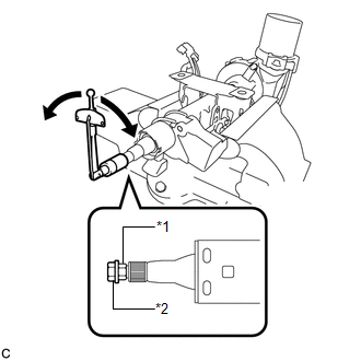
(b) Install a service nut to the steering main shaft.
Recommended service nut:
Thread diameter
12.0 mm (0.472 in.)
Thread pitch
1.25 mm (0.0492 in.)
(c) Install the steering wheel assembly set nut to the steering main shaft.
(d) Lock the steering wheel assembly set nut using the service nut.
(e) Using a torque wrench, turn the main shaft and measure the preload.
Torque:
Preload :
0.98-1.58 N·m {10-16 kgf·cm, 9-13 in·lbf}
If the preload is not as specified, replace the steering column assembly.
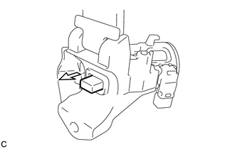
2. INSPECT STEERING LOCK OPERATION (w/o Smart Key System)
|
(a) Check that the steering lock mechanism is activated when the key is removed. |
|
|
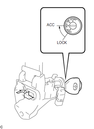
(b) Check that the steering lock mechanism is deactivated when the key is inserted and turned to the ACC position. HINT: If there is any abnormality, replace the ignition switch lock cylinder assembly or steering column upper bracket assembly. |
|
 Disassembly
DISASSEMBLY
CAUTION / NOTICE / HINT
NOTICE:
When using a vise, do not overtighten it.
PROCEDURE
1. REMOVE STEERING LOCK ACTUATOR ASSEMBLY (w/ Smart Key System)
(a) Secure the steering column ass ...
 Reassembly
REASSEMBLY
CAUTION / NOTICE / HINT
NOTICE:
When using a vise, do not overtighten it.
PROCEDURE
1. INSTALL STEERING LOCK ACTUATOR ASSEMBLY (w/ Smart Key System)
(a) Secure the steering column ass ...
Other materials about Toyota Venza:
System Description
SYSTEM DESCRIPTION
1. FUNCTION OF MAIN COMPONENTS
Component
Function
Accessory Meter Assembly
AWD Warning Light
Illuminates to warn the driver of a malfunction in the active
torque ...
Engine (ignition) switch (vehicles without smart key system)
- Starting the engine
Check that the parking brake is
set.
Check that the shift lever is set
in “P”.
Sit in the driver’s seat and firmly
depress the brake pedal.
Turn the engine switch to the “START”
position and start the engine ...
Components
COMPONENTS
ILLUSTRATION
ILLUSTRATION
ILLUSTRATION
ILLUSTRATION
ILLUSTRATION
...

0.1267