Toyota Venza: Rear Spoiler
Components
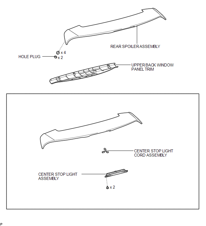
COMPONENTS
ILLUSTRATION
Removal
REMOVAL
PROCEDURE
1. REMOVE UPPER BACK WINDOW PANEL TRIM
.gif)
2. REMOVE REAR SPOILER ASSEMBLY
|
(a) Disconnect the connector. |
|
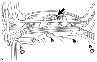
(b) Remove the 2 hole plugs.
(c) Remove the 4 bolts.
|
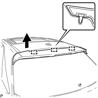
(d) Disengage the 3 pins to remove the rear spoiler assembly. |
|
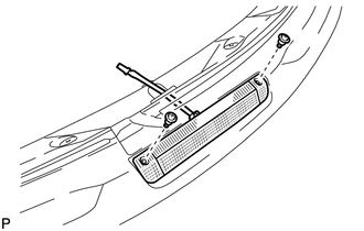
3. REMOVE CENTER STOP LIGHT ASSEMBLY
|
(a) Remove the 2 screws and center stop light assembly. |
|
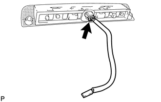
4. REMOVE CENTER STOP LIGHT CORD ASSEMBLY
|
(a) Disconnect the connector and remove the center stop light cord assembly. |
|
Installation
INSTALLATION
PROCEDURE
1. INSTALL CENTER STOP LIGHT CORD ASSEMBLY
|
(a) Connect the connector and install the center stop light cord assembly. |
|
.png)
2. INSTALL CENTER STOP LIGHT ASSEMBLY
|
(a) Install the center stop light assembly with the 2 screws to the rear spoiler assembly. |
|
.png)
3. INSTALL REAR SPOILER ASSEMBLY
|
(a) Engage the 3 pins to install the rear spoiler assembly. |
|

|
(b) Install the 4 bolts. |
|
.png)
(c) Install the 2 hole plugs.
(d) Connect the connector.
4. INSTALL UPPER BACK WINDOW PANEL TRIM
.gif)
 Installation
INSTALLATION
PROCEDURE
1. INSTALL REAR DOOR UPPER WINDOW FRAME MOULDING
(a) Engage the guide and install the rear door upper window frame moulding
to the door frame.
...
 Rear Wheel House Plate
Components
COMPONENTS
ILLUSTRATION
Installation
INSTALLATION
PROCEDURE
1. INSTALL NO. 2 ROCKER PANEL MOULDING PROTECTOR
(a) Install the No. 2 rocker panel moulding protector wi ...
Other materials about Toyota Venza:
Noise Occurs
PROCEDURE
1.
CHECK NOISE CONDITION
(a) Check from which direction the noise comes (front left or right, or rear
left or right).
OK:
The location of the noise source can be determined.
NG
GO TO STEP 3
...
Inspection
INSPECTION
PROCEDURE
1. INSPECT UNIVERSAL JOINT SPIDER ASSEMBLY
(a) Check the spider bearing axial play by turning the flange while holding
the shaft tightly.
HINT:
If necessary, replace the propeller with center bearing shaft assembly. ...
Dtc Check / Clear
DTC CHECK / CLEAR
1. CHECK DTC
(a) Connect the Techstream to the DLC3.
(b) Turn the ignition switch to ON.
(c) Turn the Techstream on.
(d) Enter the following menus: Body Electrical / Sliding Roof / Trouble Codes.
(e) Check the details of the DTC(s) (See ...

0.165