Toyota Venza: Installation
INSTALLATION
PROCEDURE
1. INSTALL NO. 1 ULTRASONIC SENSOR RETAINER
|
(a) Engage the 2 claws to install the No. 1 ultrasonic sensor retainer to the rear bumper assembly. Text in Illustration
NOTICE:
HINT:
|
|
2. INSTALL NO. 1 ULTRASONIC SENSOR
|
(a) Engage the 2 claws to install the No. 1 ultrasonic sensor to the No. 1 ultrasonic sensor retainer. Text in Illustration
NOTICE: Push the No. 1 ultrasonic sensor retainer from the outside of the rear bumper assembly when there is a gap between the No. 1 ultrasonic sensor retainer and the rear bumper assembly surface. In this case, do not push on the No .1 ultrasonic sensor. |
|
.png)
3. INSTALL ULTRASONIC SENSOR CLIP
|
(a) Engage the 4 claws to install the ultrasonic sensor clip. Text in Illustration
|
|
.png)
|
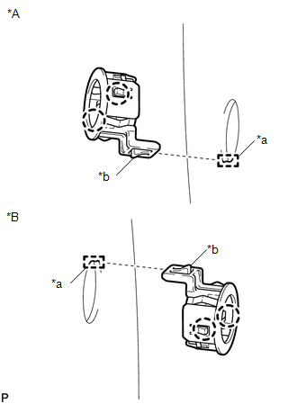
(b) Engage the clamp. Text in Illustration
|
|
.png)
(c) Connect the connector.
4. INSTALL REAR BUMPER ASSEMBLY
(See page .gif) )
)
 Removal
REMOVAL
PROCEDURE
1. REMOVE REAR BUMPER ASSEMBLY
(See page )
2. REMOVE ULTRASONIC SENSOR CLIP
(a) Disconnect the connector.
Text in Illustration
*A
...
 Brake (front)
...
Other materials about Toyota Venza:
Mass Air Flow Meter
Components
COMPONENTS
ILLUSTRATION
On-vehicle Inspection
ON-VEHICLE INSPECTION
CAUTION / NOTICE / HINT
NOTICE:
Perform the mass air flow meter inspection according to the procedure
below.
Only replace the mass air flow meter when t ...
System Diagram
SYSTEM DIAGRAM
Communication Table
Transmitting ECU (Transmitter)
Receiving ECU (Receiver)
Signal
Communication Method
Certification ECU (smart key ECU assembly)
Power management contro ...
Removal
REMOVAL
PROCEDURE
1. REMOVE REAR DOOR SCUFF PLATE RH
HINT:
Use the same procedure for the RH side and LH side (See page
).
2. DISCONNECT REAR DOOR OPENING TRIM WEATHERSTRIP RH
HINT:
Use the same procedure for the RH side and LH side (See page
).
3. ...

0.1719