Toyota Venza: Installation
INSTALLATION
PROCEDURE
1. INSTALL OUTER REAR VIEW MIRROR ASSEMBLY
|
(a) Engage the 3 claws to install the outer rear view mirror assembly as shown in the illustration. |
|
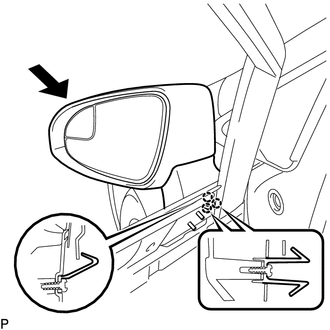
(b) Install the 3 nuts.
Torque:
8.0 N·m {82 kgf·cm, 71 in·lbf}
(c) Connect the connector.
(d) Install the hole plug.
2. INSTALL FRONT DOOR SERVICE HOLE COVER
.gif)
3. INSTALL OUTER MIRROR CONTROL ECU ASSEMBLY (w/ Memory)
4. INSTALL DOOR SIDE AIRBAG SENSOR
5. INSTALL FRONT DOOR INSIDE HANDLE SUB-ASSEMBLY
6. INSTALL FRONT DOOR TRIM BOARD SUB-ASSEMBLY
7. INSTALL COURTESY LIGHT ASSEMBLY
8. INSTALL POWER WINDOW REGULATOR MASTER SWITCH ASSEMBLY WITH FRONT DOOR ARMREST BASE PANEL (for Driver Side)
9. INSTALL POWER WINDOW REGULATOR SWITCH ASSEMBLY WITH FRONT DOOR ARMREST BASE PANEL (for Front Passenger Side)
10. INSTALL FRONT DOOR INSIDE HANDLE BEZEL PLUG
11. CONNECT CABLE TO NEGATIVE BATTERY TERMINAL
NOTICE:
When disconnecting the cable, some systems need to be initialized after the cable
is reconnected (See page ).
12. INSPECT SRS WARNING LIGHT
(See page )
 Reassembly
REASSEMBLY
PROCEDURE
1. INSTALL SIDE TURN SIGNAL LIGHT ASSEMBLY
2. INSTALL OUTER MIRROR COVER
3. INSTALL OUTER MIRROR LIGHT ASSEMBLY
4. INSTALL OUTER MIRROR
...
 Outer Rear View Mirror Cover
Components
COMPONENTS
ILLUSTRATION
Installation
INSTALLATION
PROCEDURE
1. INSTALL OUTER MIRROR COVER
(a) Engage the 7 claws to install the outer mirror cover.
...
Other materials about Toyota Venza:
Installation
INSTALLATION
CAUTION / NOTICE / HINT
NOTICE:
When disconnecting the steering intermediate shaft assembly and pinion shaft
of steering gear assembly, be sure to place matchmarks before servicing.
PROCEDURE
1. INSTALL TIE ROD ASSEMBLY LH
(a) I ...
Data List / Active Test
DATA LIST / ACTIVE TEST
1. DATA LIST
HINT:
Using the Techstream to read the Data List allows the values or states of switches,
sensors, actuators and other items to be read without removing any parts. This non-intrusive
inspection can be very useful bec ...
The distance display and buzzer
When a sensor detects an obstacle, the direction of and the approximate distance
to the obstacle are displayed and the buzzer sounds.
- Corner sensor operation and distance to an obstacle
The system operates when the vehicle approaches within the fol ...

0.1699