Toyota Venza: Front Sensor Communication Malfunction (C1AEC)
DESCRIPTION
This DTC is stored when there is an open or short circuit in the communication line between the front sensors and the ECU, or when there is a malfunction in a front sensor.
|
DTC No. |
DTC Detection Condition |
Trouble Area |
|---|---|---|
|
C1AEC |
An open or short circuit in the communication line between the front sensors and ECU or a malfunction in a front sensor during initialization mode after the engine switch is turned on (IG). |
|
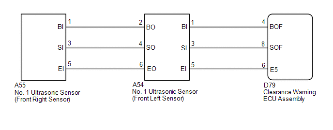
WIRING DIAGRAM
PROCEDURE
|
1. |
CHECK DTC OUTPUT (C1AEC) |
(a) Check for DTCs (See page .gif) ).
).
(b) Clear the DTCs (See page ).
(c) Recheck for DTCs (See page ).
|
Result |
Proceed to |
|---|---|
|
DTC C1AEC is output |
A |
|
No DTCs are output |
B |
| B | .gif) |
USE SIMULATION METHOD TO CHECK |
|
.gif)
|
2. |
CHECK HARNESS AND CONNECTOR (CLEARANCE WARNING ECU ASSEMBLY - FRONT LEFT SENSOR) |
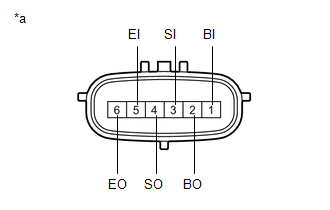
(a) Disconnect the D79 clearance warning ECU assembly connector.
(b) Disconnect the A54 No. 1 ultrasonic sensor connector.
(c) Measure the resistance according to the value(s) in the table below.
Standard Resistance:
|
Tester Connection |
Condition |
Specified Condition |
|---|---|---|
|
D79-4 (BOF) - A54-1 (BI) |
Always |
Below 1 Ω |
|
D79-8 (SOF) - A54-3 (SI) |
Always |
Below 1 Ω |
|
D79-6 (E5) - A54-5 (EI) |
Always |
Below 1 Ω |
|
D79-4 (BOF) - Body ground |
Always |
10 kΩ or higher |
|
D79-8 (SOF) - Body ground |
Always |
10 kΩ or higher |
|
D79-6 (E5) - Body ground |
Always |
10 kΩ or higher |
| NG | |
REPAIR OR REPLACE HARNESS OR CONNECTOR |
|
|
3. |
CHECK HARNESS AND CONNECTOR (FRONT LEFT SENSOR - FRONT RIGHT SENSOR) |
(a) Disconnect the A55 No. 1 ultrasonic sensor connector.
(b) Measure the resistance according to the value(s) in the table below.
Standard Resistance:
|
Tester Connection |
Condition |
Specified Condition |
|---|---|---|
|
A54-2 (BO) - A55-1 (BI) |
Always |
Below 1 Ω |
|
A54-4 (SO) - A55-3 (SI) |
Always |
Below 1 Ω |
|
A54-6 (EO) - A55-5 (EI) |
Always |
Below 1 Ω |
|
A54-2 (BO) - Body ground |
Always |
10 kΩ or higher |
|
A54-4 (SO) - Body ground |
Always |
10 kΩ or higher |
|
A54-6 (EO) - Body ground |
Always |
10 kΩ or higher |
| NG | |
REPAIR OR REPLACE HARNESS OR CONNECTOR |
|
|
4. |
INSPECT NO. 1 ULTRASONIC SENSOR (FRONT LEFT SENSOR) |
|
(a) Measure the resistance according to the value(s) in the table below. Standard Resistance:
|
|
| NG | |
REPLACE NO. 1 ULTRASONIC SENSOR (FRONT LEFT SENSOR) |
|
|
5. |
REPLACE NO. 1 ULTRASONIC SENSOR (FRONT LEFT SENSOR) |
|
|
6. |
CHECK DTC OUTPUT (C1AEC) |
(a) Clear the DTCs (See page ).
(b) Check for DTCs (See page ).
|
Result |
Proceed to |
|---|---|
|
DTC C1AEC is output |
A |
|
No DTCs are output |
B |
| B | |
END |
|
|
7. |
REPLACE NO. 1 ULTRASONIC SENSOR (FRONT RIGHT SENSOR) |
|
|
8. |
CHECK DTC OUTPUT (C1AEC) |
(a) Clear the DTCs (See page ).
(b) Check for DTCs (See page ).
|
Result |
Proceed to |
|---|---|
|
DTC C1AEC is output |
A |
|
No DTCs are output |
B |
| A | |
REPLACE CLEARANCE WARNING ECU ASSEMBLY |
| B | |
END |
 Lost Communication with ECM / PCM "A" (U0100-U0142,U0155)
DESCRIPTION
These DTCs are stored when the clearance warning ECU assembly cannot receive
and recognize several signals via the CAN communication system.
DTC No.
DTC Detection ...
 Rear Sensor Communication Malfunction (C1AED)
DESCRIPTION
This DTC is stored when there is an open or short circuit in the communication
line between the rear sensors and the ECU, or when there is a malfunction in a rear
sensor.
...
Other materials about Toyota Venza:
Compass
The compass on the inside rear view mirror indicates the direction in which
the vehicle is heading.
- Operation
To turn the compass on or off, push and hold “AUTO” for longer than 3 seconds.
- Displays and directions
Calibrating the c ...
Problem Symptoms Table
PROBLEM SYMPTOMS TABLE
HINT:
Use the table below to help determine the cause of problem symptoms. If multiple
suspected areas are listed, the potential causes of the symptoms are listed in order
of probability in the "Suspected Area" column of ...
Starter Relay Circuit High (P0617)
MONITOR DESCRIPTION
While the engine is being cranked, battery voltage is applied to terminal STA
of the ECM. If the ECM detects the Starter Control (STA) signal while the vehicle
is being driven, it determines that there is a malfunction in the STA circu ...

0.1575