
Toyota Venza: CD Sound Skips
PROCEDURE
|
1. |
CHECK CD |
|
(a) Check that the CD is not deformed or cracked. OK: No deformation or cracks on the CD |
|
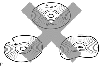
| NG | .gif) |
END (CD IS FAULTY) |
|
.gif)
|
2. |
CHECK CD |
|
(a) Check the CD. OK: The CD is clean. NOTICE: Do not use a conventional record cleaner or anti-static preservative. HINT: If dirt is on the CD surface, wipe it clean with a soft cloth from the inside to the outside in a radial direction. |
|
.png)
| NG | |
CLEAN CD |
|
|
3. |
REPLACE CD AND RECHECK |
(a) Replace the CD with a known good one and check that the malfunction disappears.
OK:
Malfunction disappears.
| OK | |
END (CD WAS FAULTY) |
|
|
4. |
CHECK RADIO AND DISPLAY RECEIVER ASSEMBLY |
(a) Check the radio and display receiver assembly installation condition.
(1) Check that the radio and display receiver assembly is properly installed.
OK:
The radio and display receiver assembly is properly installed.
| OK | |
REPLACE RADIO AND DISPLAY RECEIVER ASSEMBLY |
| NG | |
REINSTALL RADIO AND DISPLAY RECEIVER ASSEMBLY PROPERLY |
 CD cannot be Inserted / Played or CD is Ejected Right After Insertion
PROCEDURE
1.
CHECK IF A PROPER CD IS INSERTED
(a) Make sure that the CD is an audio CD or a CD with an MP3, WMA or AAC file,
and that it is not deformed, flawed, st ...
 Radio Broadcast cannot be Received or Poor Reception
PROCEDURE
1.
CHECK RADIO AND DISPLAY RECEIVER ASSEMBLY
(a) Check the radio automatic station search function.
(1) Check the radio automatic station search function b ...
Other materials about Toyota Venza:
Removal
REMOVAL
PROCEDURE
1. DISCONNECT CABLE FROM NEGATIVE BATTERY TERMINAL
CAUTION:
Wait at least 90 seconds after disconnecting the cable from the negative (-)
battery terminal to disable the SRS system.
NOTICE:
When disconnecting the cable, some systems ne ...
Capacity and distribution
Cargo capacity depends on the total weight of the occupants.
(Cargo capacity) = (Total load capacity) — (Total weight of occupants) Steps
for Determining Correct Load Limit—
(1) Locate the statement “The combined weight of occupants and cargo should ...
Diagnosis System
DIAGNOSIS SYSTEM
1. CHECK BATTERY VOLTAGE
Standard voltage:
11 to 14 V
If the voltage is below 11 V, recharge the battery before proceeding to the next
step.
2. CHECK DLC3
(a) The ECU uses ISO 15765-4 for communication. The terminal arrangement of the ...

0.1603