Toyota Venza: Horn Circuit
DESCRIPTION
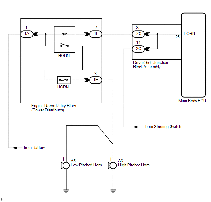
When the theft deterrent system is switched from the armed state to the alarm sounding state, the main body ECU (driver side junction block assembly) transmits a signal to cause the horn to sound at intervals of 0.4 seconds.
WIRING DIAGRAM
PROCEDURE
|
1. |
INSPECT HORNS |
(a) Press the horn switch and check if the horns sound.
|
Result |
Proceed to |
|---|---|
|
Horns sound |
A |
|
Horns do not sound |
B |
| B | .gif) |
GO TO HORN SYSTEM |
|
.gif)
|
2. |
PERFORM ACTIVE TEST USING TECHSTREAM |
(a) Connect the Techstream to the DLC3.
(b) Turn the ignition switch to ON.
(c) Turn the Techstream on.
(d) Select the item below in the Active Test and then check that the horns operate.
Main Body|
Tester Display |
Test Part |
Control Range |
Diagnostic Note |
|---|---|---|---|
|
Vehicle Horn |
Vehicle horns |
ON / OFF |
- |
OK:
The vehicle horns sound and stop correctly when operated through the Techstream.
| OK | |
PROCEED TO NEXT SUSPECTED AREA SHOWN IN PROBLEM SYMPTOMS TABLE |
| NG | |
REPLACE MAIN BODY ECU (DRIVER SIDE JUNCTION BLOCK ASSEMBLY) |
 Engine Hood Courtesy Switch Circuit
DESCRIPTION
The security courtesy switch is installed together with the hood lock. This switch
turns off when the engine hood is opened and turns on when the engine hood is closed.
WIRING DIAGRAM
...
 Security Horn Circuit
DESCRIPTION
When the theft deterrent system is switched from the armed state to the alarm
sounding state, the main body ECU (driver side junction block assembly) controls
the security horn.
WIRI ...
Other materials about Toyota Venza:
Cold Start Idle Air Control System Performance (P050A)
MONITOR DESCRIPTION
This monitor will run when the engine is started at an engine coolant temperature
of -10 to 50°C (14 to 122°F). The DTC is stored after the engine idles for 13
seconds (2 trip detection logic).
The DTC is designed to monitor the idl ...
Removal
REMOVAL
CAUTION / NOTICE / HINT
HINT:
Use the same procedure for the RH side and LH side.
The procedure listed below is for the LH side.
PROCEDURE
1. REMOVE FRONT WHEEL
2. REMOVE FRONT AXLE SHAFT NUT
3. SEPARATE FRONT SPEED SENSOR
...
Data List / Active Test
DATA LIST / ACTIVE TEST
1. DATA LIST
HINT:
Using the Techstream to read the Data List allows the values or states of switches,
sensors, actuators and other items to be read without removing any parts. This non-intrusive
inspection can be very useful bec ...

0.1296