Toyota Venza: PIG Power Supply Voltage Malfunction (C1552)
DESCRIPTION
When a problem occurs in the power steering system, the power source relay circuit is shut off to stop the power assist.
|
DTC No. |
DTC Detection Condition |
Trouble Area |
|---|---|---|
|
C1552 |
PIG power source circuit malfunction inside ECU |
|
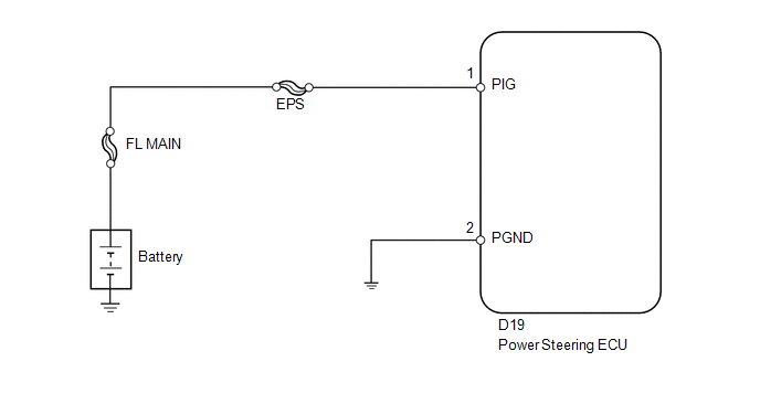
WIRING DIAGRAM
CAUTION / NOTICE / HINT
NOTICE:
- If the power steering ECU has been replaced with a new one, perform
the rotation angle sensor initialization and torque sensor zero point calibration
(See page
.gif) ).
). - Inspection the fuses for circuits related to this system before performing the following inspection procedure.
PROCEDURE
|
1. |
READ VALUE USING TECHSTREAM (PIG POWER SUPPLY) |
(a) Turn the ignition switch off.
(b) Connect the Techstream to the DLC3.
(c) Start the engine.
(d) Turn the Techstream on.
(e) Enter the following menus: Chassis / EMPS / Data List.
(f) Select the items "PIG Power Supply" in the Data List and read the value displayed on the Techstream.
EMPS|
Tester Display |
Measurement Item/Range |
Normal Condition |
Diagnostic Note |
|---|---|---|---|
|
PIG Power Supply |
Power source voltage to active motor/ Min.: 0 V Max.: 20.1531 V |
11 to 14 V |
The engine is running and power steering is operating. |
OK:
Normal condition value is displayed the Techstream.
| OK | .gif) |
REPLACE POWER STEERING ECU |
|
.gif)
|
2. |
CHECK HARNESS AND CONNECTOR (POWER STEERING ECU - BATTERY AND BODY GROUND) |
|
(a) Disconnect the connector from the power steering ECU. |
|
(b) Measure the voltage according to the value(s) in the table below.
Standard Voltage:
|
Tester Connection |
Condition |
Specified Condition |
|---|---|---|
|
D19-1 (PIG) - Body ground |
Always |
11 to 14 V |
(c) Measure the resistance according to the value(s) in the table below.
Standard Resistance:
|
Tester Connection |
Condition |
Specified Condition |
|---|---|---|
|
D19-2 (PGND) - Body ground |
Always |
Below 1 Ω |
|
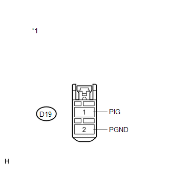
*1 |
Front view of wire harness connector (to Power Steering ECU) |
| OK | |
REPLACE POWER STEERING ECU |
| NG | |
REPAIR OR REPLACE HARNESS OR CONNECTOR |
 Assist Map Number Mismatch (C1582)
DESCRIPTION
When an incorrect ECM or brake actuator assembly (skid control ECU) is installed
after the assist map has been recorded in the power steering ECU, then DTC C1582
is stored because the ...
 Assist Map Number Un-Writing (C1581)
DESCRIPTION
The power steering ECU stores this DTC when it determines that the assist map
is not written in the ECU.
HINT:
The assist map is data written in the power steering ECU to control the ...
Other materials about Toyota Venza:
Theft Deterrent System Communication Line High Fixation (B279A)
DESCRIPTION
If the communication line (EFIO-IMI) to the transponder key ECU assembly is stuck
high output (e.g. shorted to +B), the ECM stores this DTC.
DTC No.
DTC Detection Condition
Trouble Area
B279A
...
Precaution
PRECAUTION
1. PRECAUTION FOR DISCONNECTING CABLE FROM NEGATIVE BATTERY TERMINAL
NOTICE:
When disconnecting the cable from the negative (-) battery terminal, initialize
the following system after the terminal is reconnected:
System Name
...
Installation
INSTALLATION
PROCEDURE
1. INSTALL NO. 1 COOLER THERMISTOR
(a) Install the No. 1 cooler thermistor as shown in the illustration.
Part
Length
A
34.3 mm
...

0.1293