Toyota Venza: System Diagram
SYSTEM DIAGRAM
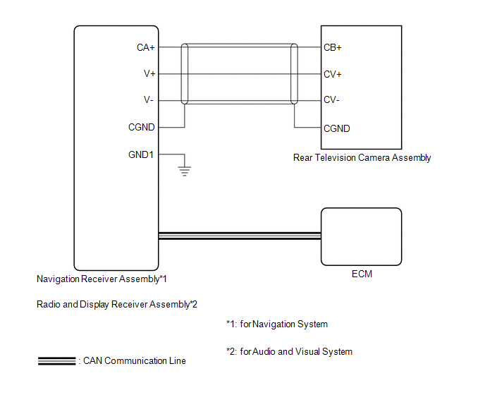 Communication Table
|
Sender |
Receiver |
Signal |
Line |
|---|---|---|---|
|
ECM |
|
Reverse signal |
CAN Communication Line |
- *1: for Navigation System
- *2: for Audio and Visual System
 Parts Location
PARTS LOCATION
ILLUSTRATION
ILLUSTRATION
...
 How To Proceed With Troubleshooting
CAUTION / NOTICE / HINT
HINT:
Use the following procedure to troubleshoot the rear view monitor system.
*: Use the Techstream.
PROCEDURE
1.
VEHICLE BROU ...
Other materials about Toyota Venza:
Diagnostic Trouble Code Chart
DIAGNOSTIC TROUBLE CODE CHART
CAN Communication System
DTC Code
Detection Item
Output ECU/Techstream Display
See page
U0100
Lost Communication with ECM / PCM
Power management ...
Installation
INSTALLATION
PROCEDURE
1. INSTALL FUEL INJECTOR ASSEMBLY
HINT:
Perform "Inspection After Repair" after replacing the fuel injector assembly
(See page ).
(a) Apply a light coat of gasoline or spindle oil to new O-rings, and
then ...
Door Courtesy Light
Components
COMPONENTS
ILLUSTRATION
Removal
REMOVAL
PROCEDURE
1. REMOVE COURTESY LIGHT ASSEMBLY
(a) Using a screwdriver wrapped with protective tape, disengage the claw.
Text in Illustration
*1
Pro ...

0.1751