Toyota Venza: Purge Valve
Components
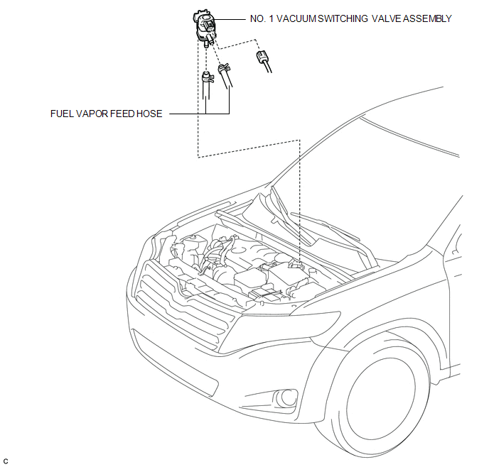
COMPONENTS
ILLUSTRATION
Inspection
INSPECTION
PROCEDURE
1. INSPECT NO. 1 VACUUM SWITCHING VALVE ASSEMBLY
|
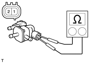
(a) Measure the resistance according to the value(s) in the table below. Standard Resistance:
If the result is not as specified, replace the No. 1 vacuum switching valve assembly. |
|
(b) Check the operation of the No. 1 vacuum switching valve assembly.
|
(1) Check that air does not flow from port F when air is applied to port E. Text in Illustration
|
|
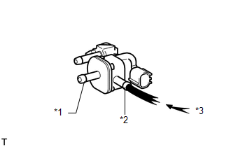
|
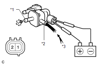
(2) Apply battery voltage to the connector, and check the VSV operation. Text in Illustration
OK:
If the result is not as specified, replace the No. 1 vacuum switching valve assembly. |
|
Removal
REMOVAL
PROCEDURE
1. REMOVE NO. 1 VACUUM SWITCHING VALVE ASSEMBLY
|
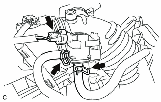
(a) Disconnect the connector and 2 fuel vapor feed hoses. |
|
|
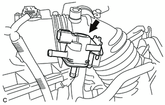
(b) Remove the No. 1 vacuum switching valve assembly. |
|
Installation
INSTALLATION
PROCEDURE
1. INSTALL NO. 1 VACUUM SWITCHING VALVE ASSEMBLY
|
(a) Install the No. 1 vacuum switching valve assembly. |
|
.png)
|
(b) Connect the connector and 2 fuel vapor feed hoses. |
|
.png)
 Pcv Valve
Components
COMPONENTS
ILLUSTRATION
Removal
REMOVAL
PROCEDURE
1. REMOVE INTAKE MANIFOLD
(a) Remove the intake manifold (See page ).
2. REMOVE VENTILATION VALVE SUB-ASSEMBLY
( ...

Other materials about Toyota Venza:
Precaution
PRECAUTION
1. IGNITION SWITCH EXPRESSIONS
HINT:
The type of ignition switch used on this model differs according to the specifications
of the vehicle. The expressions listed in the table below are used in this section.
Expression
Sw ...
Door Courtesy Switch Circuit
DESCRIPTION
The main body ECU (driver side junction block assembly) detects the condition
of the door courtesy light switch.
WIRING DIAGRAM
PROCEDURE
1.
READ VALUE USING TECHSTREAM
(a) Connect the Techstream to the DLC3 ...
Installation
INSTALLATION
PROCEDURE
1. INSTALL PARK/NEUTRAL POSITION SWITCH ASSEMBLY
(a) Move the shift lever to N.
(b) Align the protrusions of the park/neutral position switch.
Text in Illustration
*1
Protrusion
...

0.1271