Toyota Venza: Disassembly
DISASSEMBLY
PROCEDURE
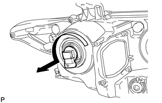
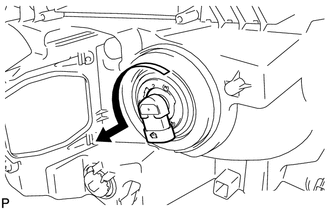
1. REMOVE NO. 2 HEADLIGHT BULB (for Halogen Headlight)
|
(a) Turn the No. 2 headlight bulb in the direction indicated by the arrow shown in the illustration, and remove it. NOTICE: Do not touch the bulb glass. |
|
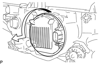
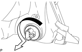
2. REMOVE LIGHT CONTROL ECU (for HID Headlight)
|
(a) Turn the light control ECU in the direction indicated by the arrow shown in the illustration, and disconnect it. NOTICE:
|
|
|
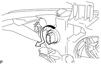
(b) Turn the socket of the light control ECU in the direction indicated by the arrow shown in the illustration, and remove it. NOTICE: Do not pull the light control ECU with the socket connected. |
|
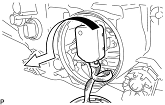
3. REMOVE DISCHARGE HEADLIGHT BULB (for HID Headlight)
|
(a) Release the set spring as shown in the illustration and remove the discharge headlight bulb. NOTICE: Do not touch the bulb glass. |
|
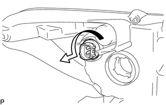
4. REMOVE NO. 1 HEADLIGHT BULB (for Halogen Headlight)
|
(a) Turn the No. 1 headlight bulb in the direction indicated by the arrow shown in the illustration, and remove it. NOTICE: Do not touch the bulb glass. |
|
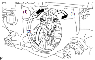
5. REMOVE FRONT TURN SIGNAL LIGHT BULB
(a) for Halogen Headlight:
|
(1) Turn the front turn signal light socket with the front turn signal light bulb in the direction indicated by the arrow shown in the illustration, and remove them as a unit. |
|
(b) for HID Headlight:
|
(1) Turn the front turn signal light socket with the front turn signal light bulb in the direction indicated by the arrow shown in the illustration, and remove them as a unit. |
|
(c) Remove the front turn signal light bulb from the front turn signal light socket.
6. REMOVE FRONT SIDE MARKER LIGHT BULB
|
(a) Turn the front side marker light socket with the front side marker light bulb in the direction indicated by the arrow shown in the illustration, and remove them as a unit. |
|
(b) Remove the front side marker light bulb from the front side marker light socket.
 Components
COMPONENTS
ILLUSTRATION
ILLUSTRATION
...
 Removal
REMOVAL
CAUTION / NOTICE / HINT
HINT:
Use the same procedure for the RH and LH sides.
The procedure described below is for the LH side.
PROCEDURE
1. PRECAUTION (for HID Headligh ...
Other materials about Toyota Venza:
Cellular Phone Registration Failure
PROCEDURE
1.
CHECK USAGE CONDITION
(a) Check that the vehicle and cellular phone meet the following conditions:
NOTICE:
If changing cellular phone settings, updating software, etc. is necessary, make
sure to obtain the per ...
Installation
INSTALLATION
CAUTION / NOTICE / HINT
HINT:
Use the same procedure for the RH side and LH side.
The following procedure is for the LH side.
The rear speed sensor is a component of the rear axle hub and bearing
assembly. If the sensor malf ...
How To Proceed With Troubleshooting
CAUTION / NOTICE / HINT
HINT:
Use the following procedure to troubleshoot.
PROCEDURE
1.
VEHICLE BROUGHT TO WORKSHOP
NEXT
2.
CUSTOMER PR ...

0.1763