Toyota Venza: Removal
REMOVAL
PROCEDURE
1. REMOVE REAR DOOR SCUFF PLATE RH
HINT:
Use the same procedure for the RH side and LH side (See page
.gif) ).
).
2. DISCONNECT REAR DOOR OPENING TRIM WEATHERSTRIP RH
HINT:
Use the same procedure for the RH side and LH side (See page
).
3. REMOVE TONNEAU COVER ASSEMBLY (w/ Tonneau Cover)
4. REMOVE DECK BOARD ASSEMBLY
5. REMOVE NO. 3 DECK BOARD SUB-ASSEMBLY
6. REMOVE DECK SIDE TRIM BOX LH
7. REMOVE NO. 2 DECK BOARD SUB-ASSEMBLY
8. REMOVE DECK SIDE TRIM BOX RH
9. REMOVE NO. 1 DECK BOARD
10. REMOVE REAR SEAT SUB FLOOR PANEL ASSEMBLY
11. REMOVE REAR FLOOR FINISH PLATE
12. REMOVE REAR SEAT HEADREST ASSEMBLY RH
13. REMOVE REAR SEAT CENTER HEADREST ASSEMBLY
14. REMOVE REAR SEAT INNER TRACK BRACKET COVER RH
15. REMOVE REAR SEAT OUTER TRACK BRACKET COVER RH
16. DISCONNECT REAR SEAT RECLINING CONTROL CABLE SUB-ASSEMBLY
17. REMOVE REAR SEAT ASSEMBLY RH
18. REMOVE RECLINING REMOTE CONTROL BEZEL
HINT:
Use the same procedure for the RH side and LH side (See page
).
19. REMOVE LUGGAGE HOLD BELT STRIKER ASSEMBLY
HINT:
Use the same procedure for the RH side and LH side (See page
).
20. DISCONNECT REAR SEAT OUTER BELT ASSEMBLY
HINT:
Use the same procedure for the RH side and LH side (See page
).
21. REMOVE DECK TRIM SIDE PANEL ASSEMBLY RH
22. REMOVE ROOF SIDE INNER GARNISH ASSEMBLY RH
HINT:
Use the same procedure for the RH side and LH side (See page
).
23. REMOVE DOOR CONTROL RECEIVER
|
(a) Disconnect the connector. |
|
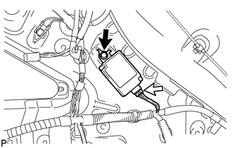
(b) Remove the bolt and the door control receiver.
 Components
COMPONENTS
ILLUSTRATION
ILLUSTRATION
ILLUSTRATION
ILLUSTRATION
...
 Installation
INSTALLATION
PROCEDURE
1. INSTALL DOOR CONTROL RECEIVER
(a) Install the door control receiver with the bolt.
(b) Connect the connector.
2 ...
Other materials about Toyota Venza:
Open or Short Circuit in ABS Motor Relay Circuit (C0273/13)
DESCRIPTION
The ABS motor relay supplies power to the ABS pump motor. While the ABS is activated,
the ECU turns the motor relay on and operates the ABS pump motor.
If the voltage supplied to the motor relay (+BM) is below the DTCs detection
threshold due ...
Radio Broadcast cannot be Received or Poor Reception
PROCEDURE
1.
CHECK RADIO AND DISPLAY RECEIVER ASSEMBLY
(a) Check the radio automatic station search function.
(1) Check the radio automatic station search function by activating it.
Result
Proceed to
...
Installation
INSTALLATION
PROCEDURE
1. INSTALL CONSOLE BOX ASSEMBLY
(a) Connect the connectors.
(b) Engage the 2 claws.
(c) Install the screw and 2 clips.
...

0.1521