Toyota Venza: Motor Rotation Angle Sensor Malfunction (C1528)
DESCRIPTION
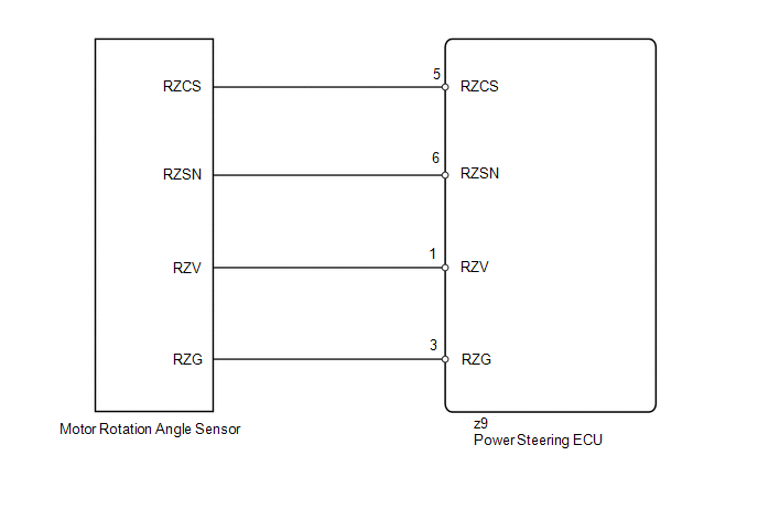
The motor rotation angle sensor detects the motor rotation angle and sends this information to the power steering ECU.
|
DTC No. |
DTC Detection Condition |
Trouble Area |
|---|---|---|
|
C1528 |
Motor rotation angle sensor malfunction |
|
WIRING DIAGRAM
CAUTION / NOTICE / HINT
NOTICE:
If the power steering ECU and steering column assembly have been replaced, perform
the rotation angle sensor initialization and torque sensor zero point calibration
(See page .gif) ).
).
PROCEDURE
|
1. |
CHECK CONNECTOR CONNECTION CONDITION |
(a) Check the installation condition of the motor rotation angle sensor connector.
OK:
Motor rotation angle sensor connector is securely connected to the power steering ECU.
| NG | .gif) |
CONNECT CONNECTOR |
|
.gif)
|
2. |
READ VALUE USING TECHSTREAM (MOTOR ROTATION ANGLE SENSOR) |
(a) Turn the ignition switch off.
(b) Connect the Techstream to the DLC3.
(c) Turn the ignition switch to ON.
(d) Turn the Techstream on.
(e) Enter the following menus: Chassis / EMPS / Data List.
(f) Select the item "Motor Rotation Angle" in the Data List and read the value displayed on the Techstream.
EMPS|
Tester Display |
Measurement Item/Range |
Normal Condition |
Diagnostic Note |
|---|---|---|---|
|
Motor Rotation Angle |
Motor rotation angle/ Min.: 0 deg Max.: 360 deg |
During steering operation, motor rotation angle value changes from 0 to 360° |
The engine is running and steering wheel is being turned. |
OK:
During steering operation, motor rotation angle value changes from 0 to 360°.
| OK | |
REPLACE POWER STEERING ECU |
|
|
3. |
CHECK STEERING COLUMN ASSEMBLY |
|
(a) Disconnect the connector from the motor rotation angle sensor. |
|
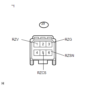
(b) Measure the resistance according to the value(s) in the table below.
Standard Resistance:
|
Tester Connection |
Condition |
Specified Condition |
|---|---|---|
|
z9-6 (RZSN) - z9-3 (RZG) |
Always |
75.2 to 112.8 Ω |
|
z9-1 (RZV) - z9-3 (RZG) |
Always |
27.6 to 41.4 Ω |
|
z9-5 (RZCS) - z9-3 (RZG) |
Always |
73.2 to 110.8 Ω |
|
*1 |
Front view of wire harness connector (to Motor Rotation Angle Sensor) |
| OK | |
REPLACE POWER STEERING ECU |
| NG | |
REPLACE STEERING COLUMN ASSEMBLY |
 IG Power Supply Voltage Malfunction (C1551)
DESCRIPTION
The power steering ECU distinguishes the ignition switch status as ON or off
through the IG power source circuit.
DTC No.
DTC Detection Condition
Troub ...
 Vehicle Speed Signal Malfunction (C1541)
DESCRIPTION
The power steering ECU receives vehicle speed signals from the brake actuator
assembly (skid control ECU) via CAN communication. The ECU provides appropriate
assisting force in accord ...
Other materials about Toyota Venza:
Problem Symptoms Table
PROBLEM SYMPTOMS TABLE
HINT:
Use the table below to help determine the cause of problem symptoms.
If multiple suspected areas are listed, the potential causes of the symptoms
are listed in order of probability in the "Suspected Area" ...
Terminals Of Ecu
TERMINALS OF ECU
1. CHECK CERTIFICATION ECU (SMART KEY ECU ASSEMBLY)
(a) Disconnect the D25 certification ECU (smart key ECU assembly) connector.
(b) Measure the voltage and resistance according to the value(s) in the table
below.
HINT:
Measure the va ...
Power Window Switch Malfunction (B2312)
DESCRIPTION
The power window regulator motor assembly is operated by the power window regulator
master switch assembly or power window regulator switch assembly. The power window
regulator motor assembly has motor, regulator and ECU functions.
This DTC i ...

0.1744