Toyota Venza: Parts Location
PARTS LOCATION
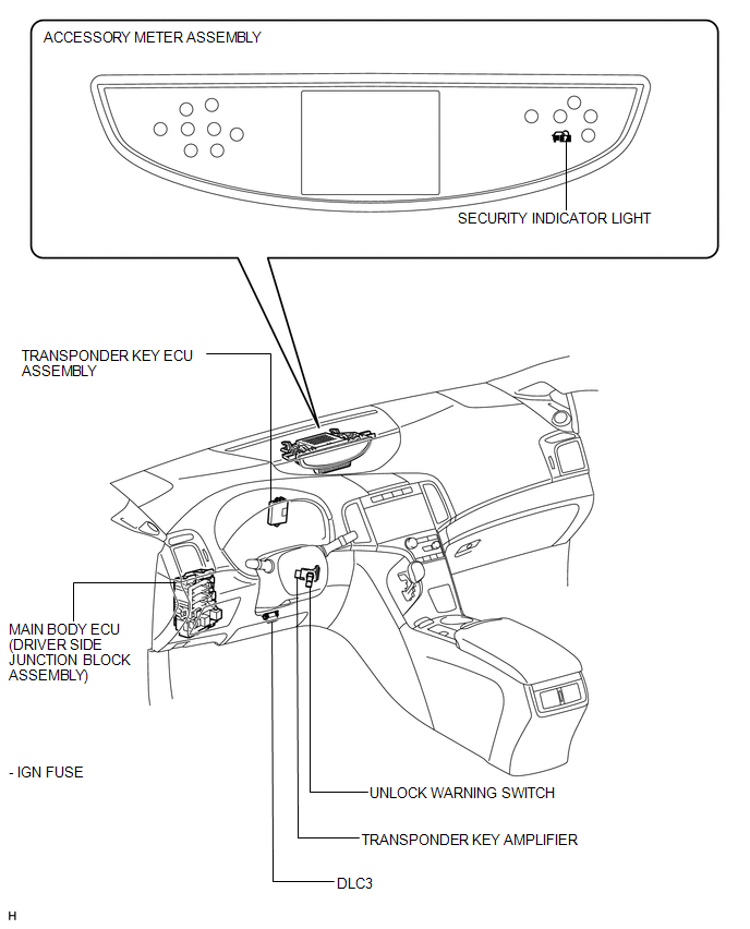
ILLUSTRATION
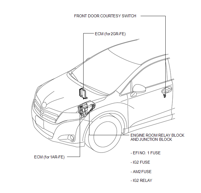
ILLUSTRATION
 Precaution
PRECAUTION
1. PRECAUTION FOR DISCONNECTING CABLE FROM NEGATIVE BATTERY TERMINAL
NOTICE:
When disconnecting the cable from the negative (-) battery terminal, initialize
the following system after ...
 System Description
SYSTEM DESCRIPTION
1. ENGINE IMMOBILISER SYSTEM DESCRIPTION
The engine immobiliser system is designed to prevent the vehicle from being stolen.
This system uses the transponder key ECU assembly th ...
Other materials about Toyota Venza:
Blower Motor Circuit
DESCRIPTION
The blower motor is operated by signals from the A/C amplifier. Blower motor
speed signals are transmitted in accordance with changes in the duty ratio.
WIRING DIAGRAM
CAUTION / NOTICE / HINT
NOTICE:
Inspect the fuses for circuits related ...
Speed Signal Circuit
DESCRIPTION
The headlight leveling ECU assembly receives the vehicle speed signal from the
combination meter assembly.
HINT:
A voltage of 12 V or 5 V is output from each ECU and then input to the
combination meter. The signal is changed to a p ...
Sound of Portable Player cannot be Heard from Speakers or Sound is Low
PROCEDURE
1.
CHECK PORTABLE PLAYER SETTINGS
(a) Check the portable player settings.
(1) Check that the volume is not set to "0".
(2) Check that mute is off.
(b) Check that the sound of the portable player can be h ...

0.1311